


•
View status messages that inform you if tests are completed successfully
•
View error messages that inform you of problems encountered during testing
CAUTION: Use the system diagnostics to test only your computer. Using
this program with other computers may cause invalid results or error
messages.
NOTE: Some tests for specific devices require user interaction. Always
ensure that you are present at the computer terminal when the diagnostic
tests are performed.
For more information, see
.
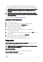
Running the ePSA diagnostics
1
Power-on the computer.
2
As the computer boots, press the F12 key as the Dell logo appears.
3
On the boot menu screen, select the
Diagnostics
option.
4
Click the arrow key at the bottom left corner.
Diagnostics front page is displayed.
5
Press the arrow in the lower-right corner to go to the page listing.
The items detected are listed.
6
To run a diagnostic test on a specific device, press Esc and click
Yes
to stop the
diagnostic test.
7
Select the device from the left pane and click
Run Tests
.
8
If there are any issues, error codes are displayed.
Note the error code and validation number and contact Dell.
Diagnostics
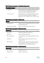
Power and battery-status light/ hard-drive activity light:
Indicates the battery-
charge status or the hard-drive activity.
NOTE: Press Fn+H to toggle this light between power and battery-status
light and hard-drive activity light.
Hard-drive activity light
Turns on when the computer reads from or writes to the hard drive.
Power and battery-status light
Indicates the power and battery-charge status.
95
Summary of Contents for Inspiron 13 7000 Series
Page 19: ...3 Lift the battery off the palm rest assembly 19 ...
Page 22: ...2 Peel the coin cell battery off the keyboard bracket 22 ...
Page 25: ...2 Lift the heat sink off the system board 25 ...
Page 28: ...4 Lift the fan off the keyboard bracket 28 ...
Page 31: ...5 Lift the right speaker off the palm rest assembly 31 ...
Page 34: ...3 Lift the power adapter port off the palm rest assembly 34 ...
Page 42: ...7 Gently lift the display assembly off the palm rest assembly 42 ...
Page 46: ...5 Lift the I O board off the palm rest assembly 46 ...
Page 54: ...14 Lift the system board off the palm rest assembly 54 ...
Page 62: ...5 Slide and lift the touchpad from the slot on the palm rest assembly 62 ...
Page 70: ...5 Lift the keyboard off the palm rest assembly 70 ...
Page 74: ...Procedure After performing all the prerequisites we are left with the palm rest 74 ...


