background image

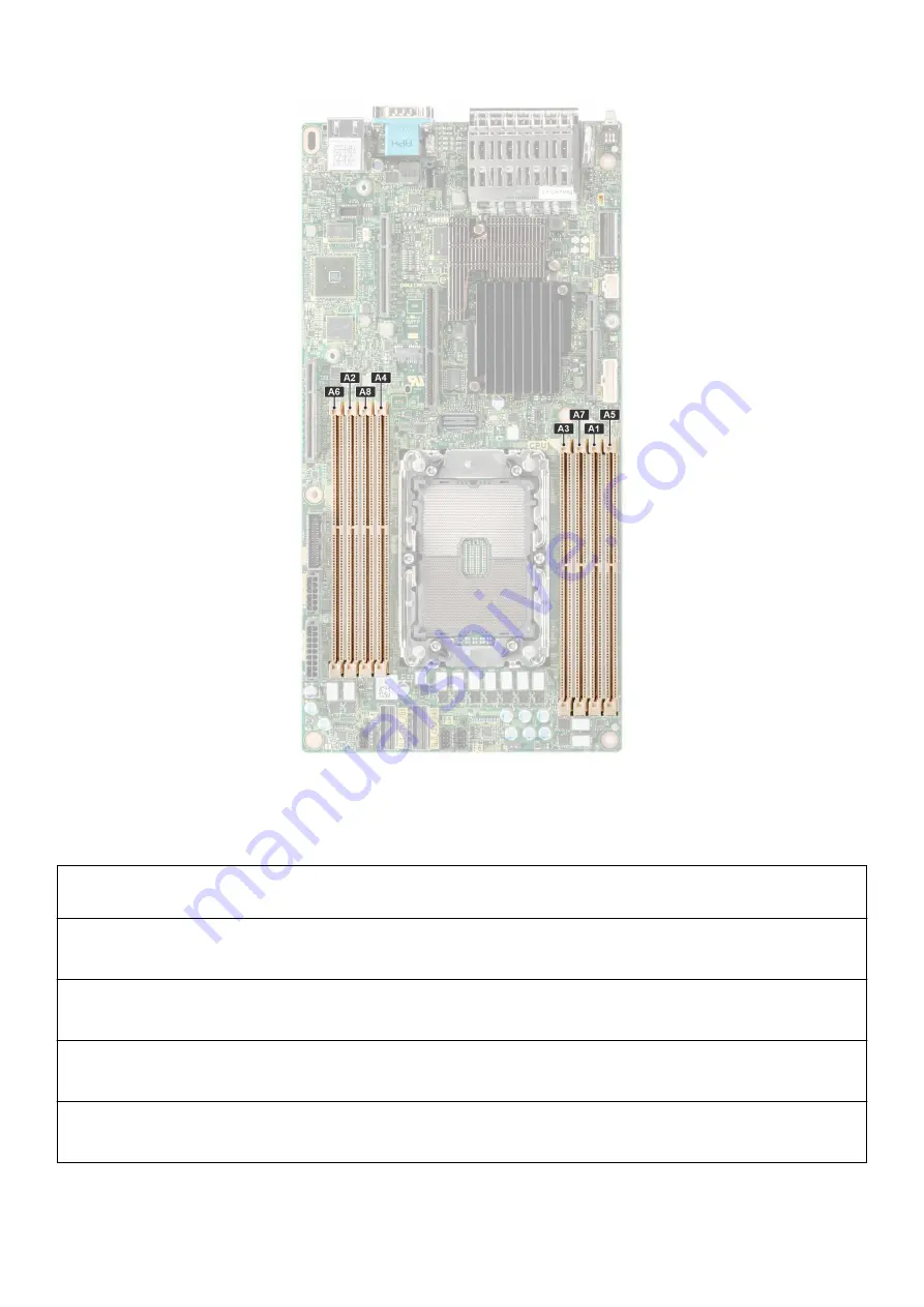
Figure 45. Memory sockets on the system board

The following table shows the memory populations and operating frequencies for the supported configurations:

Table 22. Memory population 

DIMM Type

DIMM Ranking

Capacity

DIMM rated voltage

and speed

Operating speed for

DIMMs per Channel

(DPC)

RDIMM

1R

8 GB

DDR4 (1.2V), 3200

MT/s, 2933 MT/s or

2666 MT/s

3200 MT/s

RDIMM

2R

16 GB, 32 GB, 64 GB

DDR4 (1.2V), 3200

MT/s, 2933 MT/s or

2666 MT/s

3200 MT/s

LRDIMM

4R

128 GB

DDR4 (1.2V), 3200

MT/s, 2933 MT/s or

2666 MT/s

3200 MT/s

Intel Optane PMem
200 Series DIMM

1R

128 GB

DDR4 (1.2V), 3200

MT/s, 2933 MT/s or

2666 MT/s

3200 MT/s

56

Installieren und Entfernen von Systemkomponenten

Summary of Contents for EMC PowerEdge XR11

Page 1: ...Dell EMC PowerEdge XR11 Installation and Service Manual Part Number E72S Regulatory Type E72S001 September 2021 Rev A01 ...

Page 2: ...ardware oder vor Datenverlust und zeigt wie diese vermieden werden können WARNUNG Mit WARNUNG wird auf eine potenziell gefährliche Situation hingewiesen die zu Sachschäden Verletzungen oder zum Tod führen kann 2021 Dell Inc oder ihre Tochtergesellschaften Alle Rechte vorbehalten Dell EMC und andere Marken sind Marken von Dell Inc oder entsprechenden Tochtergesellschaften Andere Marken können Marke...

Page 3: ...oad and install OS drivers 24 Herunterladen von Treibern und Firmware 24 Chapter 4 Mindestvalidierung der POST und System Management Konfiguration 25 Minimum configuration to POST 25 Konfigurationsvalidierung 25 Fehlermeldungen 26 Chapter 5 Installieren und Entfernen von Systemkomponenten 28 Safety instructions 28 Vor der Arbeit an Komponenten im Inneren Ihres Systems 29 Nach der Arbeit im Inneren...

Page 4: ...n eines Speichermoduls 59 Processor and heat sink module 60 Removing the processor and heat sink module 60 Removing the processor from the processor heat sink module 62 Installieren des Prozessors im Prozessorkühlkörpermodul 63 Installing the processor and heat sink module 67 Erweiterungskarten und Erweiterungskarten Riser 69 Richtlinien zur Installation von Erweiterungskarten 70 Removing the expa...

Page 5: ...r Front Accessed configuration 105 Removing the power button control panel for Front Accessed configuration 106 Installing the power button control panel for Front Accessed configuration 107 Rugged Kit MIL 901E und MIL 461G 108 Installing the MIL 901E and MIL 461G rugged kit 109 Chapter 6 Upgrade Kits 111 Chapter 7 Jumper und Anschlüsse 112 System board connectors 112 Jumper Einstellungen auf der ...

Page 6: ...Chapter 10 Dokumentationsangebot 125 6 Contents ...

Page 7: ...ument bietet eine Übersicht über das System Informationen zur Installation und zum Austausch von Komponenten Diagnosetools und Richtlinien die bei der Installation bestimmter Komponenten befolgt werden müssen 1 Über dieses Dokument 7 ...

Page 8: ...d by Dell Damage caused by unauthorized and invalidated hardware installation will null and void the system warranty NOTE For more information see the Dell EMC PowerEdge XR11 Technical Specifications on the product documentation page Topics Front view of the system Rear view of the system Status LED Bedienfeld Power button control panel Das Systeminnere Locating the Express Service Code and Servic...

Page 9: ...ns Service Tag iDRAC MAC address and LOM 1 MAC address Figure 2 Front view of Front Accessed configuration Table 2 Features available on the front view of Front Accessed configuration Item Ports panels or slots Icon Description 1 PCIe expansion card riser 1 slot 1 N A Enables you to connect PCIe expansion card installed on riser 1 2 Serial port Enables you to connect a serial device to the system ...

Page 10: ...em identification button Press the system ID button To locate a particular system within a rack To turn the system ID on or off To reset iDRAC press and hold the button for more than 16 seconds NOTE To reset iDRAC using system ID ensure that the system ID button is enabled in the iDRAC setup If the system stops responding during POST press and hold the system ID button for more than 5 seconds to e...

Page 11: ...ser 2 and 3 slot 2 and 3 N A Enables you to connect PCIe expansion card installed on riser 2 and 3 in the system 5 Power supply unit PSU2 Indicates the PSU2 or redundant PSU 6 Power supply unit PSU1 Indicates the PSU1 or primary PSU 7 USB 2 0 port This port is USB 2 0 compliant 8 USB 3 0 port This port is USB 3 0 compliant 9 VGA port Enables you to connect a display device to the system 10 4 x 25 ...

Page 12: ... panels and slots Icon Description 1 Status LED control panel N A Contains the system health system ID status LED Status LED Enables you to identify any failed hardware components There are up to five status LEDs and an overall system health LED Chassis health and system ID bar For more information see the Status LED indicators section 2 Drives N A Enables you to install up to 4x 2 5 inch SAS SATA...

Page 13: ...e im Abschnitt Systemdiagnose und Anzeigecodes Power button control panel Figure 6 Power button control panel for Front Accessed configuration Table 6 Power button control panel Item Indicator or button Icon Description 1 Power button Gibt an ob das System ein oder ausgeschaltet ist Betätigen Sie den Betriebsschalter um das System manuell ein bzw auszuschalten NOTE Drücken Sie den Betriebsschalter...

Page 14: ...able 7 Power button control panel Item Indicator or button Icon Description 1 Power button Gibt an ob das System ein oder ausgeschaltet ist Betätigen Sie den Betriebsschalter um das System manuell ein bzw auszuschalten NOTE Drücken Sie den Betriebsschalter um ein ACPI konformes Betriebssystem ordnungsgemäß herunterzufahren 2 iDRAC Direct LED indicator N A The iDRAC Direct LED indicator lights up t...

Page 15: ...1 Karte optional 4 Prozessor und Kühlkörpermodul 5 Speichermodulsteckplätze 8 6 Prozessorkühlgehäuse 7 Kühlungslüfter 6 8 Informationsschild 9 Laufwerkträger 10 Rückwandplatine 11 PCI Kühlgehäuse 12 Stromzwischenplatine Power Interposer Board PIB 13 Riser 2 und 3 14 Netzteileinheiten PowerEdge XR11 System overview 15 ...

Page 16: ... 3 14 Netzteileinheiten Locating the Express Service Code and Service Tag The unique Express Service Code and Service Tag are used to identify the system The information tag is located on the front of the Rear Accessed configuration and rear of the Front Accessed configuration The information tag includes system information such as the Service Tag Express Service Code Manufacture date NIC MAC addr...

Page 17: ...Service Tag ST Express Service Code Exp Svc Code and Manufacture Date Mfg Date The Exp Svc Code is used by Dell EMC to route support calls to the appropriate personnel Alternatively the Service Tag information is located on a label on the left wall of Rear Accessed configuration and right wall of the Front Accessed configuration Etikett mit Systeminformationen Das Etikett mit Systeminformationen b...

Page 18: ...Abbildung 11 Serviceinformationen 18 PowerEdge XR11 System overview ...

Page 19: ...ilität Detaillierte Informationen zu den Schienenlösungen die mit Ihrem System kompatibel sind finden Sie in der Dell EMC Enterprise Matrix für Schienendimensionierung und Rackkompatibilität die unter https i dell com sites csdocuments Business_solutions_engineering Docs_Documents en rail rack matrix pdf verfügbar ist PowerEdge XR11 System overview 19 ...

Page 20: ...tails zu Schienentypen und ihren Funktionen Schienen Einstellbereich für verschiedene Arten von Rack Montage Flanschen Schienentiefe mit und ohne Kabelführungszubehör Racktypen die für verschiedene Arten von Rack Montageflansche unterstützt werden 20 PowerEdge XR11 System overview ...

Page 21: ...te Handbuch das mit dem System ausgeliefert wurde ANMERKUNG Informationen zum Managen der grundlegenden Einstellungen und Funktionen des Systems finden Sie im Dell EMC PowerEdge XR11 Referenzhandbuch für BIOS und UEFI auf der Produktdokumentationsseite iDRAC Konfiguration Der Integrated Dell Remote Access Controller iDRAC wurde entwickelt um Ihre Produktivität als Systemadministrator zu steigern u...

Page 22: ...manuals Product Support page of your system Documentation NOTE To determine the most recent iDRAC release for your platform and for latest documentation version see KB article https www dell com support article sln308699 NOTE To access iDRAC ensure that you connect the ethernet cable to the iDRAC dedicated network port or use the iDRAC Direct port by using the USB cable You can also access iDRAC t...

Page 23: ...m Documentation Dell recommends using Lifecycle Controller to install the OS since all required drivers are installed on the system NOTE To determine the most recent iDRAC release for your platform and for latest documentation version see KB article at https www dell com support article sln308699 OpenManage Deployment Toolkit www dell com openmanagemanuals OpenManage Deployment Toolkit Dell certif...

Page 24: ...port article sln308699 Herunterladen von Treibern und Firmware Es wird empfohlen die aktuellen Versionen von BIOS Treibern und Systemverwaltungs Firmware auf dem System herunterzuladen in zu installieren Voraussetzungen Stellen Sie sicher dass Sie vor dem Download der Treiber und der Firmware den Cache Ihres Webbrowsers leeren Schritte 1 Rufen Sie www dell com support drivers auf 2 Geben Sie die S...

Page 25: ...rufen Diese Informationen bilden eine einzigartige Konfiguration die mit einer der qualifizierten Konfigurationen verglichen wird die in einer von iDRAC verwalteten Tabelle gespeichert sind Jedem der Konfigurationselemente werden ein oder mehrere Sensoren zugewiesen Während des POST Vorgangs wird jeder Konfigurationsvalidierungsfehler im Systemereignisprotokoll SEL Lifecycle LC Protokoll protokoll...

Page 26: ...rgumente Rückwandplatine Prozessor Kabel oder andere Komponenten Detaillierte Beschreibung Bei der Systemkonfigurationsprüfung wurde das in der Meldung genannte Problem beobachtet Empfohlene Antwortmaßnahme Führen Sie die folgenden Schritte aus und wiederholen Sie den Vorgang 1 Trennen Sie das Gerät vom Netzanschluss 2 Überprüfen Sie die ordnungsgemäße Kabelverbindung und die Komponentenplatzierun...

Page 27: ...Tabelle 14 Fehlermeldung HWC8011 fortgesetzt Fehlercode HWC8011 Schweregrad Kritisch Mindestvalidierung der POST und System Management Konfiguration 27 ...

Page 28: ...ou To avoid injury do not attempt to lift the System by yourself CAUTION Ensure that two or more people lift the system horizontally from the box and place it on a flat surface rack lift or into the rails WARNING Opening or removing the System cover while the System is powered on may expose you to a risk of electric shock WARNING Do not operate the System without the cover for a duration exceeding...

Page 29: ...d tested by Dell Damage caused by unauthorized and invalidated hardware installation will null and void the system warranty Vor der Arbeit an Komponenten im Inneren Ihres Systems Voraussetzungen Befolgen Sie die Sicherheitshinweise im Abschnitt Sicherheitshinweise Schritte 1 Schalten Sie das System und alle angeschlossenen Peripheriegeräte aus 2 Trennen Sie das System und die Peripheriegeräte von ...

Page 30: ...80 or equivalent 65 30 stranding Optionale Frontverkleidung Entfernen der Frontverkleidung Voraussetzungen 1 Befolgen Sie die Sicherheitshinweise im Abschnitt Sicherheitshinweise 2 Befolgen Sie die Schritte im Abschnitt Vor der Arbeit an Komponenten im Inneren Ihres Systems Schritte 1 Entfernen Sie die Schrauben auf beiden Seiten der Blende 2 Halten Sie die Blende an den Rändern fest und entfernen...

Page 31: ...seitig zugänglicher Konfiguration Blendenfilter Removing the bezel filter for Rear Accessed configuration Prerequisites 1 Follow the safety guidelines listed in the Safety instructions 2 Follow the procedure listed in the Before working inside your system 3 Remove the front bezel Steps 1 Remove the metal filter bracket using the tab marked LIFT on the inside face of the bezel Installieren und Entf...

Page 32: ... bezel filter for Rear Accessed configuration Prerequisites 1 Follow the safety guidelines listed in the Safety instructions 2 Remove the front bezel Steps 1 Place the new filter in the bezel cavity under the filter bracket Ensure that the filter is smooth and aligned in the allowed slot 2 Align the filter bracket with painted surface facing the filter and align the bracket to the guides on the be...

Page 33: ...afety guidelines listed in the Safety instructions 2 Follow the procedure listed in the Before working inside your system Steps 1 Using a 1 4 inch flat head or Phillips 2 screwdriver rotate the lock counterclockwise to the unlock position 2 Lift the release latch until the system cover slides back 3 Lift the cover from the system Installieren und Entfernen von Systemkomponenten 33 ...

Page 34: ...emoving the system cover for Rear Accessed configuration Figure 20 Removing the system cover for Front Accessed configuration Next steps Replace the system cover 34 Installieren und Entfernen von Systemkomponenten ...

Page 35: ... are connected and routed properly and no tools or extra parts are left inside the system Steps 1 Align the tabs on the system cover with the guide slots on the system 2 Close the system cover release latch 3 Using a 1 4 inch flat head or Phillips 2 screwdriver rotate the lock clockwise to the lock position Figure 21 Installing the system cover for Rear Accessed configuration Installieren und Entf...

Page 36: ...igure 22 Installing the system cover for Front Accessed configuration Next steps Follow the procedure listed in Nach der Arbeit im Inneren des Systems 36 Installieren und Entfernen von Systemkomponenten ...

Page 37: ...u Datenverlust führt 1 Follow the safety guidelines listed in the Safety instructions 2 Follow the procedure listed in the Vor der Arbeit an Komponenten im Inneren Ihres Systems NOTE The procedure to remove the air shrouds is the same for Rear Accessed and Front Accessed configurations Steps Holding the air shroud at both the ends and lift the air shroud out of the system Figure 23 Removing the PC...

Page 38: ...in the Safety instructions 2 Follow the procedure listed in the Vor der Arbeit an Komponenten im Inneren Ihres Systems NOTE The procedure to install the air shrouds is the same for Rear Accessed and Front Accessed configurations Steps 1 Align the guide pins on the system with guides on the air shroud 2 Lower the air shroud into the system until it is firmly seated 38 Installieren und Entfernen von...

Page 39: ...5 Installing the PCI air shroud Figure 26 Installing the processor air shroud Next steps Follow the procedure listed in Nach der Arbeit im Inneren des Systems Installieren und Entfernen von Systemkomponenten 39 ...

Page 40: ...latinenanschluss verbunden ist 2 Halten Sie die blauen Laschen fest und heben Sie den Lüfter aus dem Lüftergehäuse ANMERKUNG Wenn Sie Lüfter 5 und 6 aus einem System mit erweitertem Kühlkörpermodul entfernen möchten entfernen Sie das Prozessor und Kühlkörpermodul Abbildung 27 Entfernen eines Kühlungslüfters Nächste Schritte Setzen Sie den Kühlungslüfter wieder ein Installieren des Kühlungslüfters ...

Page 41: ...l handelt Abbildung 28 Einsetzen eines Kühlungslüfters Nächste Schritte 1 Falls zuvor entfernt setzen Sie das Kühlgehäuse wieder ein 2 Befolgen Sie die Anweisungen unter Nach der Arbeit im Inneren des Systems Intrusion switch module This is a service technician replaceable part only Removing the intrusion switch module Prerequisites 1 Follow the safety guidelines listed in the Safety instructions ...

Page 42: ...ame for Rear Accessed and Front Accessed configurations NOTE Ensure that you note the routing of all the cables as you remove them from the system board Route the intrusion switch cable properly when you replace it to prevent the cable from being pinched or crimped Steps 1 Align and insert the intrusion switch module until it is firmly seated in the slot on the system 2 Using the Phillips 1 screwd...

Page 43: ... guidelines listed in the Safety instructions 2 If installed remove the front bezel CAUTION To maintain proper system cooling drive blanks must be installed in all empty drive slots NOTE The procedure to remove the drive blank is the same for Rear Accessed and Front Accessed configurations Steps Press the release button and slide the drive blank out of the drive slot Figure 31 Removing a drive bla...

Page 44: ...ufwerk online ist blinkt die grüne Aktivitäts Fehleranzeige während das Laufwerk ausgeschaltet wird Wenn alle Laufwerksanzeigen aus sind kann das Laufwerk ausgebaut werden Weitere Informationen hierzu finden Sie in der Dokumentation zum Speicher Controller https www dell com storagecontrollermanuals VORSICHT Bevor Sie versuchen bei laufendem System ein Laufwerk zu entfernen oder einzusetzen vergew...

Page 45: ...acht werden VORSICHT Um Datenverlust zu vermeiden stellen Sie sicher dass das Betriebssystem das Installieren von Laufwerken im Hot Swap Verfahren unterstützt Informationen hierzu finden Sie in der mit dem Betriebssystem gelieferten Dokumentation VORSICHT Wenn ein Hot Swap fähiges Ersatzlaufwerk bei eingeschaltetem System installiert wird wird automatisch mit der Neuerstellung des Laufwerks begonn...

Page 46: ...n Sie gegebenenfalls die Frontverkleidung an Removing the drive from the drive carrier Prerequisites 1 Follow the safety guidelines listed in the Safety instructions Steps 1 Using a Phillips 1 screwdriver remove the screws from the slide rails on the drive carrier NOTE If the drive carrier has Torx screw use Torx 6 for 2 5 inch drive 2 Lift the drive out of the drive carrier 46 Installieren und En...

Page 47: ...e drive carrier ensure that the screws are torqued to 4 in lbs Steps 1 Insert the drive into the drive carrier with the drive connector facing towards the rear of the carrier 2 Align the screw holes on the drive with the screws holes on the drive carrier 3 Using a Phillips 1 screwdriver secure the drive to the drive carrier with the screws NOTE If the drive carrier has Torx screw use Torx 6 for 2 ...

Page 48: ...Figure 36 Installing a drive into the drive carrier Next steps 1 Replace the drive carrier 48 Installieren und Entfernen von Systemkomponenten ...

Page 49: ...in the Vor der Arbeit an Komponenten im Inneren Ihres Systems 3 Remove all the drives 4 Remove the PCI air shroud 5 Disconnect the drive backplane cables from the connectors on backplane NOTE The procedure to remove the drive backplane is the same for Rear Accessed and Front Accessed configurations CAUTION To prevent damage to the drives and backplane remove the drives from the system before remov...

Page 50: ... air shroud 4 Disconnect the drive backplane cables from the connectors on the system board NOTE Route the cables properly when you replace them to prevent the cables from being pinched or crimped NOTE The procedure to install the drive backplane is the same for Rear Accessed and Front Accessed configurations Steps 1 Align the guide pins on the backplane with the guides on the system 2 Insert the ...

Page 51: ...iser Konfiguration 1 Vorderseitig zugänglich ASSY CHAS RAF 4HD 3PCI 1U XR11 4 x 2 5 Zoll NVMe ausschließlic h H755 Adapter Y C0 1 R1B R2 R3 2 Vorderseitig zugänglich ASSY CHAS RAF 4HD 3PCI 1U XR11 4 x 2 5 Zoll NVMe ausschließlic h S150 Direktanschlu ss SL Y C0 1 R1B R2 R3 3 Vorderseitig zugänglich ASSY CHAS RAF 4HD 3PCI 1U XR11 4 x 2 5 Zoll SAS SATA H345 Adapter Y C0 1 R1B R2 R3 4 Vorderseitig zug...

Page 52: ...änglich ASSY CHAS NAF 4HD 3PCI 1U XR11 4 x 2 5 Zoll SAS SATA H345 Adapter Y C0 1 R1B R2 R3 10 Rückseitig zugänglich ASSY CHAS NAF 4HD 3PCI 1U XR11 4 x 2 5 Zoll SAS SATA H755 Adapter Y C0 1 R1B R2 R3 11 Rückseitig zugänglich ASSY CHAS NAF 4HD 3PCI 1U XR11 4 x 2 5 Zoll SAS SATA HBA355i Adapter Y C0 1 R1B R2 R3 12 Rückseitig zugänglich ASSY CHAS NAF 4HD 3PCI 1U XR11 4 x 2 5 Zoll SATA ausschließlic h ...

Page 53: ...uss auf Rückwandplatine Abbildung 41 Kabelführung SL2 NVMe Kabel von der Hauptplatine zur 4 x 2 5 Zoll Laufwerkrückwandplatine Tabelle 17 SL2 NVMe Kabel von der Hauptplatine zur 4 x 2 5 Zoll Laufwerkrückwandplatine Von Um BP_PWR Stromanschluss auf Stromzwischenplatine PWR Stromanschluss auf Rückwandplatine SL2_CPU_PA1 NVMe Signalanschluss auf Hauptplatine BP_DST_PB1 NVMe Signalanschluss auf Rückwa...

Page 54: ...Stromanschluss auf Stromzwischenplatine PWR Stromanschluss auf Rückwandplatine CTRL_SRC_SA1_PA1 NVMe Signalanschluss auf PERC Adapter BP_DST_PA1 NVMe Signalanschluss auf Rückwandplatine BP_DST_PB1 NVMe Signalanschluss auf Rückwandplatine Abbildung 43 Kabelführung SAS Kabel vom PERC zur 4 x 2 5 Zoll Laufwerkrückwandplatine 54 Installieren und Entfernen von Systemkomponenten ...

Page 55: ...ückwandplatine SL3_PCH_SA1 SATA Signalanschluss auf der Hauptplatine BP_DST_SA1 SATA Signalanschluss auf Rückwandplatine Systemspeicher System memory guidelines The PowerEdge XR11 System supports DDR4 registered DIMMs RDIMMs load reduced DIMMs LRDIMMs and Intel Optane PMem 200 Series System memory holds the instructions that are executed by the processor Your system contains 8 memory sockets organ...

Page 56: ...voltage and speed Operating speed for DIMMs per Channel DPC RDIMM 1R 8 GB DDR4 1 2V 3200 MT s 2933 MT s or 2666 MT s 3200 MT s RDIMM 2R 16 GB 32 GB 64 GB DDR4 1 2V 3200 MT s 2933 MT s or 2666 MT s 3200 MT s LRDIMM 4R 128 GB DDR4 1 2V 3200 MT s 2933 MT s or 2666 MT s 3200 MT s Intel Optane PMem 200 Series DIMM 1R 128 GB DDR4 1 2V 3200 MT s 2933 MT s or 2666 MT s 3200 MT s 56 Installieren und Entfer...

Page 57: ...tückung Informationen zur Arbeitsspeicherbestücku ng Einzelprozessor Bestückungsreihenfolge im Optimierungsmodus unabhängige Kanäle A 1 A 2 A 3 A 4 A 5 A 6 A 7 A 8 Es sind 1 2 4 6 8 DIMMs zulässig Speichermodule unterschiedlicher Kapazität können kombiniert werden vorausgesetzt es werden die betreffenden zusätzlichen Regeln zur Arbeitsspeicherbestückung befolgt ANMERKUNG Beispielsweise können Sie ...

Page 58: ...zungen 1 Befolgen Sie die Sicherheitshinweise unter Safety instructions 2 Befolgen Sie die Anweisungen unter Vor der Arbeit an Komponenten im Inneren Ihres Systems 3 Entfernen Sie das Prozessorkühlgehäuse ANMERKUNG Das Verfahren zum Entfernen des Speichermoduls ist bei rückseitig zugänglichen und vorderseitig zugänglichen Konfigurationen gleich WARNUNG Die Speichermodule sind auch nach dem Ausscha...

Page 59: ...ichermodulen VORSICHT Um eine ordnungsgemäße Systemkühlung zu gewährleisten müssen in allen nicht belegten Speichersockeln Speichermodulplatzhalter installiert werden Entfernen Sie Speichermodulplatzhalter nur wenn Sie in diesen Sockeln Speicher installieren möchten Schritte 1 Machen Sie den entsprechenden Speichermodulsockel ausfindig VORSICHT Fassen Sie jedes Speichermodul nur an den Kartenrände...

Page 60: ...folgen Sie die Anweisungen unter Nach der Arbeit im Inneren des Systems 3 Um zu überprüfen ob das Speichermodul richtig installiert wurde drücken Sie F2 und navigieren Sie zu Hauptmenü des System Setups System BIOS Speichereinstellungen In den Memory Settings Speichereinstellungen muss die Systemspeichergröße mit der aktualisierten Kapazität des installierten Speichers übereinstimmen 4 Wenn die Sy...

Page 61: ... then using a Torx T30 tool loosen the nuts on the heat sink in the order that is mentioned below a Loosen the first nut completely b Loosen the nut diagonally opposite to the nut you loosened first c Repeat the procedure for the remaining two nut Figure 48 Loosening the nuts and set the anti tilt wires to the unlocked position 2 Set the anti tilt wires to the unlocked position inward position 3 L...

Page 62: ...edure to remove the processor is the same for Rear Accessed and Front Accessed configurations CAUTION You may find the CMOS battery loss or CMOS checksum error that is displayed during the first instance of powering on the system after the processor or system board replacement which is expected To fix this simply go to setup option to configure the system settings Steps 1 Place the heat sink with ...

Page 63: ...er all the corners are released from the heat sink lift the carrier from the pin 1 corner of the heat sink Figure 51 Removing the processor carrier Next steps Replace the processor Installieren des Prozessors im Prozessorkühlkörpermodul Voraussetzungen 1 Befolgen Sie die Sicherheitshinweise unter Safety instructions 2 Befolgen Sie die Anweisungen unter Vor der Arbeit an Komponenten im Inneren Ihre...

Page 64: ... 1 Markierung auf dem Träger auf die Kontaktstift 1 Markierung auf dem Prozessor ausgerichtet ist bevor Sie den Träger auf den Prozessor legen ANMERKUNG Stellen Sie sicher dass der Prozessor und der Träger vor der Installation des Kühlkörpers auf der Ablage abgelegt wurden Abbildung 52 Einbauen des Prozessorträgers 3 Richten Sie den Prozessorschacht auf die Halterung aus indem Sie die Halterung mi...

Page 65: ...m die Paste in einer dünnen Spirale oben auf den Kühlkörper aufzutragen Abbildung 54 Auftragen der Wärmeleitpaste auf dem Kühlkörper VORSICHT Wenn zu viel Wärmeleitpaste aufgetragen wird kann die überschüssige Wärmeleitpaste in Kontakt mit dem Prozessorsockel kommen und diesen verunreinigen ANMERKUNG Die Spritze für die Wärmeleitpaste ist zum einmaligen Gebrauch bestimmt nur Entsorgen Sie die Spri...

Page 66: ...f dem Kühlkörper einrastet VORSICHT Drücken Sie nicht auf die Kühlkörperlamellen Das könnte die Lamellen beschädigen ANMERKUNG Stellen Sie sicher dass die Markierung von Kontaktstift 1 auf dem Kühlkörper mit der Markierung von Kontaktstift 1 auf dem Träger ausgerichtet ist bevor Sie den Kühlkörper auf dem Prozessorträger platzieren ANMERKUNG Stellen Sie sicher dass die Verriegelungsfunktionen auf ...

Page 67: ...ructions 2 Follow the procedure listed in the Vor der Arbeit an Komponenten im Inneren Ihres Systems 3 Remove the processor air shroud NOTE The procedure to install the heat sink is the same for Rear Accessed and Front Accessed configurations Steps 1 Set the anti tilt wires to the unlocked position on the heat sink inward position 2 Align the pin 1 indicator of the heat sink to the system board an...

Page 68: ...sition and then using the Torx T30 tool tighten the captive nuts 8 in lbf on the heat sink in the order below a Tighten the first nut completely b Tighten the nut diagonally opposite to the nut you tighten first c Repeat the procedure for the remaining two nuts 68 Installieren und Entfernen von Systemkomponenten ...

Page 69: ...e Controller wird ein Systemereignis aufgezeichnet wenn ein Erweiterungskarten Riser nicht unterstützt wird oder fehlt Dies verhindert nicht dass sich das System dennoch einschalten lässt Wenn jedoch eine F1 F2 Pause mit einer Fehlermeldung auftritt finden Sie weitere Informationen im Abschnitt Troubleshooting für Erweiterungskarten im Troubleshooting Handbuch Dell EMC PowerEdge Server unter www d...

Page 70: ... Erweiterungsk arten Riser PCIe Steckplätze Steuern des Prozessors Höhe Baulänge Steckplatzbrei te Config0 R1B R2 R3 Hinten zugängliche Konfiguration 1 Prozessor 1 Low Profile Halbe Baulänge x8 2 Volle Bauhöhe Halbe Baulänge x16 3 Volle Bauhöhe Halbe Baulänge x16 Konfig1 R1B R2 R3 Vorne zugängliche Konfiguration 1 Prozessor 1 Low Profile Halbe Baulänge x8 2 Low Profile Halbe Baulänge x16 3 Volle B...

Page 71: ...zuerst installiert werden und dabei die angegebene Steckplatzpriorität erhalten Alle anderen Erweiterungskarten müssen nach Kartenpriorität und in der Reihenfolge der Steckplatzpriorität installiert werden Tabelle 27 Konfiguration 0 R1B R2 R3 bei rückseitig zugänglicher Konfiguration Kartentyp Steckplatzpriorität Maximale Anzahl an Karten Interner PERC Adapter LP 1 1 Externer Dell Adapter FH 3 2 2...

Page 72: ...icher Konfiguration Kartentyp Steckplatzpriorität Maximale Anzahl an Karten Interner PERC Adapter LP 1 1 Externer Dell Adapter FH 3 2 2 GPU FH 2 3 2 Mellanox NIC 100Gb FH 2 3 2 Mellanox NIC 25Gb FH 2 3 2 Broadcom NIC 25Gb FH 2 3 2 Broadcom NIC 25Gb LP 1 1 Broadcom NIC 10Gb FH 2 3 2 Broadcom NIC 10Gb LP 1 1 Broadcom NIC 1Gb FH 3 2 2 Broadcom NIC 1Gb LP 1 1 Intel NIC 25Gb FH 2 3 2 Intel NIC 25Gb LP ...

Page 73: ...configurations Steps 1 For riser 1 using the Phillips 2 screwdriver loosen the blue thumbscrew 2 Holding the blue touch points lift the expansion card riser from the riser connector on the system board Figure 62 Removing Riser 1 3 For riser 2 and 3 using Phillips 2 loosen the blue thumbscrews Hold the blue touch points and lift the expansion card riser from the riser connector on the system board ...

Page 74: ...enten im Inneren Ihres Systems 3 If removed install the expansion cards into the expansion card risers and connect all the riser cables NOTE The procedure to install the expansion card risers is the same for Rear Accessed and Front Accessed configurations Steps 1 For Riser 1 hold the blue touch points on the riser and align the connector with the connector on system board Figure 64 Installing Rise...

Page 75: ...Arbeit im Inneren des Systems 2 Install any device drivers required for the card as described in the documentation for the card Removing an expansion card from the expansion card riser Prerequisites 1 Follow the safety guidelines listed in the Safety instructions 2 Follow the procedure listed in the Vor der Arbeit an Komponenten im Inneren Ihres Systems 3 Remove the expansion card risers NOTE The ...

Page 76: ...ed If a shorter card is installed the blue retention latch is not applicable Figure 67 Removing expansion card from Riser 2 and 3 3 For riser 2 and 3 using Phillip 2 screwdriver loosen the screw and pull the card to disconnect from the connector on the expansion card riser 76 Installieren und Entfernen von Systemkomponenten ...

Page 77: ...r an empty expansion card slot to maintain Federal Communications Commission FCC certification of the system The brackets also keep dust and dirt out of the system and aid in proper cooling and airflow inside the system Figure 69 Installing filler bracket in Riser 1 5 For riser 2 and 3 install the filler bracket and tighten the screw using Phillips 2 screwdriver Installieren und Entfernen von Syst...

Page 78: ... For instructions see the documentation accompanying the card NOTE The procedure to install the T4 GPU card and the expansion card is the same for Rear Accessed and Front Accessed configurations Steps 1 Pull and lift the expansion card retention latch lock to open 2 If installed remove the filler bracket NOTE Store the filler bracket for future use Filler brackets must be installed in empty expans...

Page 79: ... and close the card holder and side card holder 6 Push the side holder and ensure that the latch hook holds the riser cover Figure 72 Installing expansion card in Riser 1 NOTE The blue retention latch is only used when a half length card is installed If a shorter card is installed the blue retention latch is not applicable 7 For Riser 2 and 3 to remove the filler bracket remove the screw using Phi...

Page 80: ...ector with the connector on the expansion card riser 9 Insert the card until firmly seated into the connector on the riser 10 Using Phillips 2 screwdriver tighten the screw on the expansion card riser Figure 74 Installing single width GPU in Riser 2 and 3 80 Installieren und Entfernen von Systemkomponenten ...

Page 81: ...nd configuration of the faulty one For more information about the Part replacement configuration see the Lifecycle Controler User s Guide at https www dell com idracmanuals Optionale BOSS S1 Karte Removing the BOSS S1 card Prerequisites 1 Follow the safety guidelines listed in the Safety instructions 2 Follow the procedure listed in the Before working inside your system NOTE The procedure to remov...

Page 82: ...beit an Komponenten im Inneren des Systems ANMERKUNG Das Verfahren zum Installieren der BOSS S1 Karte ist für die rückseitig zugänglichen und vorderseitig zugänglichen Konfigurationen gleich Schritte 1 Richten Sie den BOSS S1 Kartenanschluss auf die Anschlüsse auf der Hauptplatine aus 2 Drücken Sie die BOSS S1 Karte nach unten bis sie vollständig eingesetzt ist Abbildung 77 Installieren der BOSS S...

Page 83: ...isconnect from the connector on the BOSS S1 card Figure 78 Removing the M 2 SSD module Next steps If applicable install the M 2 SSD module Installing M 2 SSD module Prerequisites 1 Follow the safety guidelines listed in the Safety instructions 2 Follow the procedure listed in Before working inside your system 3 Remove the BOSS S1 card NOTE The procedure to install the M 2 SSD module is the same fo...

Page 84: ...Sicherheitshinweisen die mit dem System geliefert wurden 1 Befolgen Sie die Sicherheitshinweise im Abschnitt Sicherheitshinweise 2 Befolgen Sie die Schritte im Abschnitt Vor der Arbeit an Komponenten im Inneren Ihres Systems 3 Entfernen Sie den Erweiterungskarten Riser 1 4 Trennen Sie gegebenenfalls die Strom und Datenkabel von den Erweiterungskarten ANMERKUNG Die Vorgehensweise zum Entfernen der ...

Page 85: ...riehalteklammer nicht verbiegen während Sie eine Batterie installieren oder entfernen Abbildung 81 Installieren der Systembatterie Nächste Schritte 1 Falls zutreffend installieren Sie eine Erweiterungskarte in Erweiterungskarten Riser 1 2 Installieren Sie den Erweiterungskarten Riser 1 3 Befolgen Sie die Schritte im Abschnitt Nach der Arbeit an Komponenten im Inneren Ihres Systems 4 Vergewissern S...

Page 86: ...en Riser 1 ANMERKUNG Das Verfahren zum Entfernen des internen USB Schlüssels ist bei rückseitig zugänglichen und vorderseitig zugänglichen Konfigurationen gleich Schritte Entfernen Sie den USB Speicherschlüssel aus dem USB Anschluss auf Riser 1 Abbildung 82 Entfernen des internen USB Schlüssels Nächste Schritte Setzen Sie den internen USB Schlüssel wieder ein Installing internal USB key Prerequisi...

Page 87: ...100 der Systemlast und arbeitet daher mit höherer Effizienz Das Netzteil im Ruhezustand überwacht die Ausgangsspannung des aktiven Netzteils Wenn die Ausgangsspannung des aktiven Netzteils abfällt kehrt das Netzteil im Ruhezustand in einen aktiven Zustand zurück Wenn ein Zustand in dem beide Netzteile aktiv sind effizienter ist als ein sich Ruhezustand befindliches Netzteil kann das aktive Netztei...

Page 88: ...fen die korrekte Kühlung und den Luftstrom innerhalb des Systems aufrechtzuerhalten Abbildung 84 Entfernen eines Netzteilplatzhalters Nächste Schritte Installieren Sie das Netzteil oder den Netzteilplatzhalter Einsetzen des Netzteilplatzhalters Voraussetzungen 1 Befolgen Sie die Sicherheitshinweise unter Safety instructions 2 Befolgen Sie die Anweisungen im Kapitel Before working inside your syste...

Page 89: ...arm an falls er beim Entfernen des Netzteils im Weg ist Hinweise zum Kabelführungsarm finden Sie in der Dokumentation zum Rack unter https www dell com poweredgemanuals ANMERKUNG Das PowerEdge XR11 System verfügt über zwei Arten von Stromversorgungseinheiten Netzteilen PSUs Die Netzteile mit schwarzen Bändern sind für die rückseitig zugängliche Konfiguration konzipiert während die Netzteile mit bl...

Page 90: ...ie maximale Ausgangsleistung identisch ist ANMERKUNG Die maximale Ausgangsleistung in Watt ist auf dem Netzteiletikett angegeben 3 Entfernen Sie den Netzteilplatzhalter ANMERKUNG Das PowerEdge XR11 System verfügt über zwei Arten von Stromversorgungseinheiten Netzteilen PSUs Die Netzteile mit schwarzen Bändern sind für die rückseitig zugängliche Konfiguration konzipiert während die Netzteile mit bl...

Page 91: ...dem Betrieb austauschen oder hinzufügen lassen Sie dem System etwa 15 Sekunden Zeit um das Netzteil zu erkennen und seinen Status zu ermitteln Die Netzteilredundanz greift unter Umständen erst wenn die Erkennung abgeschlossen wurde Die Statusanzeige des Netzteils leuchtet grün sobald das Netzteil ordnungsgemäß arbeitet ANMERKUNG Für bestimmte Premium Konfigurationen mit hohem Energieverbrauch ist ...

Page 92: ...the PCI air shroud 4 Remove both PSUs 5 Disconnect all the cables that are connected to the system board intrusion switch Fan1 Fan 2 and Fan 3 from the power interposer board PIB NOTE The procedure to remove the power interposer board PIB is the same for Rear Accessed and Front Accessed configurations Steps 1 Using a Phillips 2 screwdriver remove the screws securing the power interposer board to t...

Page 93: ...r board PIB is the same for Rear Accessed and Front Accessed configurations Steps 1 Align the slots on the PIB with the hook on the system and slide it into place 2 Using Phillips 2 screwdriver tighten the screws to secure the PIB to the system Figure 91 Installing the power interposer board 3 Reconnect all the required cables Next steps 1 Install the PSU 2 Install the PCI air shroud 3 Follow the ...

Page 94: ...orking inside your system 3 Remove the following components a System cover b Expansion card risers c Air shrouds d Memory modules e Processor and heat sink module f Internal USB memory key if installed g BOSS S1 card h Disconnect all cables from the system board CAUTION Take care not to damage the system identification button while removing the system board from the system NOTE The procedure to re...

Page 95: ...ck the new system board assembly CAUTION Heben Sie die Systemplatinenbaugruppe nicht an einem Speichermodul einem Prozessor oder anderen Komponenten an CAUTION Take care not to damage the system identification button while placing the system board into the chassis NOTE Do not remove the processor socket cover until the system board is assembled in the system and ready for installation of the proce...

Page 96: ...ice tag is not backed up in the backup flash device enter the system service tag manually See the Manually update the Service Tag using System Setup section c Update the BIOS and iDRAC versions Re enable the Trusted Platform Module TPM See the Upgrading the Trusted Platform Module section 4 If you are not using Easy Restore import your new or existing iDRAC Enterprise license For more information ...

Page 97: ...ld is empty Ensure that you enter the correct service tag Once the service tag is entered it cannot be updated or changed 5 Click OK Trusted Platform Module This is a service technician replaceable part only Upgrading the Trusted Platform Module Removing the TPM Prerequisites NOTE Ensure the operating system is compatible with the TPM version you are installing Ensure that you download and install...

Page 98: ...nitialisieren des TPM für Benutzer 2 Die TPM Status TPM Status ändert sich zu Enabled Aktiviert Initialisieren des TPM 1 2 für Benutzer Schritte 1 Drücken Sie beim Start des System F2 um das System Setup aufzurufen 2 Klicken Sie im Bildschirm System Setup Hauptmenü auf System BIOS Systemsicherheitseinstellungen 3 Wählen Sie in der Option TPM Sicherheit Eingeschaltet mit Vorstart Messungen aus 4 Wä...

Page 99: ...Steps 1 Using the Phillips 2 screwdriver remove the screws that secure the left ear handle Figure 96 Removing the left ear handle for Rear Accessed configuration 2 Disconnect the status LED control panel cable from the system board connector NOTE Observe the routing of the cable as you remove it from the system 3 Using the Torx 8 screwdriver remove the screws that secure the left control panel ass...

Page 100: ...Remove the expansion card riser 1 NOTE If necessary please remove the backplane signal and power cables Steps 1 Align and insert the status LED control panel assembly in the slot on the system 2 Route the status LED control panel cable through the guide slots in the system and connector on system board NOTE Route the cable properly to prevent the cable from being pinched or crimped 3 Using the Tor...

Page 101: ...ser 1 2 Install the processor and heat sink module 3 Install the air shrouds 4 Follow the procedure listed in the After working inside your system Removing the power button control panel for Rear Accessed configuration Prerequisites 1 Follow the safety guidelines listed in the Safety instructions 2 Follow the procedure listed in the Vor der Arbeit an Komponenten im Inneren Ihres Systems 3 Remove t...

Page 102: ...u remove it from the system 3 Using the Torx 8 screwdriver remove the screws that secure the right control panel assembly 4 Hold the power button control panel assembly and remove the control panel along with the cable from the system NOTE Die Zahlen auf dem Bild zeigen nicht die genauen Schritte Die Zahlen dienen der Darstellung der Sequenz Figure 101 Removing the power button control panel for R...

Page 103: ...t control panel in the slot on the system 3 Connect the power button control panel cable to the connector on the system board 4 Using the Torx 8 screwdriver tighten the screws that secure the right control panel to the system NOTE Die Zahlen auf dem Bild zeigen nicht die genauen Schritte Die Zahlen dienen der Darstellung der Sequenz Figure 102 Installing the power button control panel for Rear Acc...

Page 104: ...your system 3 Remove the air shrouds 4 Remove the processor and heat sink module 5 Remove the expansion card riser 1 NOTE If required remove the backplane power and signal cables Steps 1 Disconnect the status LED control panel cable from the system board connector NOTE Observe the routing of the cable as you remove it from the system 2 Using the Torx 8 screwdriver remove the screws that secure the...

Page 105: ...ouds 4 Remove the processor heat sink module 5 Remove the expansion card riser 1 NOTE If required remove the backplane power and signal cables Steps 1 Align and insert the status LED control panel assembly in the slot on the system 2 Route the status LED control panel cable through the guide slots in the system and connector on system board NOTE Route the cable properly to prevent the cable from b...

Page 106: ...1 Steps 1 Loosen the three screws to remove the left ear for the Front Accessed configuration 2 Disconnect the power button control panel cable from the system board connector and remove the cable from cable clip NOTE Observe the routing of the cable as you remove it from the system 3 Using the Phillips 2 screwdriver remove the screws that secure the left rack ear 4 Using the Torx 8 screwdriver re...

Page 107: ... Follow the procedure listed in the Before working inside your system 3 Remove the expansion card riser 1 Steps 1 Align and insert the power button control panel in the slot on the system 2 Route the power button control panel cable through the side wall of the system NOTE Route the cable properly to prevent the cable from being pinched or crimped 3 Connect the power button control panel cable to ...

Page 108: ...rewdriver tighten the screws and secure the rack left ear Next steps 1 Install the expansion card riser 1 2 Follow the procedure listed in the After working inside your system Rugged Kit MIL 901E und MIL 461G Das Rugged Kit MIL 901E und MIL 461G bietet robusten Schutz für den PowerEdge XR11 Server Das Rugged Kit MIL 901E und MIL 461G besteht aus den folgenden Komponenten Robuste Netzteilhalterung ...

Page 109: ...rugged bracket NOTE The kit consists of screws Use three screws on the bottom side of the chassis and remaining three screws above the bracket Figure 110 Installing the 901E and MIL 461G power supply rugged bracket 2 Align the left edge of the drive retention bracket to the guide slots on the left side of the drive module Using a Phillips 2 screwdriver secure the 901E and MIL 461G drive rugged bra...

Page 110: ...lide the latch to left and then right until seated firmly 4 Install the front bezel for Rear Accessed configuration 5 Using a Phillips 2 screwdriver tighten one screw to the system cover Next steps Follow the procedure listed in Nach der Arbeit im Inneren des Systems 110 Installieren und Entfernen von Systemkomponenten ...

Page 111: ...g the SSDs Processors See Installing the processor Heat sink See Installing the heat sink Storage controller cards See Installing the expansion card into the expansion card riser HBA CNA 3rd party card Network cards Power supplies See Installing the power supply units Cables N A Rail Kits N A Bezel See Installing the bezel Risers See Installing an expansion card riser Power cords N A 6 Upgrade Kit...

Page 112: ...können das System deaktiviert und Kennwörter zurückgesetzt werden Um Komponenten und Kabel korrekt zu installieren müssen Sie in der Lage sein die Anschlüsse auf der Systemplatine zu identifizieren Themen System board connectors Jumper Einstellungen auf der Systemplatine Deaktivieren eines verlorenen Kennworts System board connectors Figure 112 System board jumpers and connectors 1 IO_Riser2 Riser...

Page 113: ... deaktiviert und Sie können kein neues Kennwort festlegen NVRAM_CLR Die BIOS Konfigurationseinstellungen bleiben beim Systemstart erhalten Die BIOS Konfigurationseinstellungen werden beim Systemstart gelöscht VORSICHT Gehen Sie beim Ändern der BIOS Einstellungen vorsichtig vor Die BIOS Schnittstelle ist für fortgeschrittene Benutzer vorgesehen Es können Änderungen vorgenommen werden die dazu führe...

Page 114: ...tzt werden ANMERKUNG Wenn Sie ein neues System bzw Setup Kennwort festlegen während der Jumper die Kontaktstiften 4 und 6 belegt deaktiviert das System beim nächsten Start die neuen Kennwörter 5 Schließen Sie die Peripheriegeräte wieder an und schließen Sie das System an die Steckdose an und schalten Sie das System anschließend ein 6 Schalten Sie das System aus 7 Entfernen Sie die Systemabdeckung ...

Page 115: ... has an error Run the appropriate Online Diagnostics test Restart the system and run embedded diagnostics ePSA If the drives are configured in a RAID array restart the system and enter the host adapter configuration utility program Temperature indicator The indicator turns solid amber if the system experiences a thermal error for example the ambient temperature is out of range or there is a fan fa...

Page 116: ...ersists see the Getting help section PCIe indicator The indicator turns solid amber if a PCIe card experiences an error Restart the system Update any required drivers for the PCIe card Reinstall the card If the problem persists see the Getting help section NOTE For more information about the supported PCIe cards see the Expansion card installation guidelines section System health and system ID ind...

Page 117: ...s verwendet wird Sie können iDRAC Direct konfigurieren indem Sie ein USB auf Mikro USB Typ AB Kabel verwenden das Sie mit Ihrem Laptop oder Tablet verbinden können Die Kabellänge darf 0 91 m 3 Fuß nicht überschreiten Die Leistung kann von der Qualität des Kabels abhängen In der folgenden Tabelle wird die iDRAC Direct Aktivität bei aktivem iDRAC Direct Port beschrieben Tabelle 33 iDRAC Direct LED A...

Page 118: ...Daten nicht gesendet oder empfangen werden Die Verbindungsanzeige leuchtet gelb und die Aktivitätsanzeige leuchtet nicht Zeigt an dass die NIC mit einem gültigen Netzwerk mit einer Geschwindigkeit unter der maximalen Port Geschwindigkeit verbunden ist und Daten nicht gesendet oder empfangen werden Die Verbindungsanzeige blinkt grün und es herrscht keine Aktivität Zeigt an dass die NIC Erkennung üb...

Page 119: ...ett verfügen z B über ein EPP Etikett Extended Power Performance Der gleichzeitige Einsatz von Netzteilen aus früheren Generationen von Dell PowerEdge Servern wird nicht unterstützt sogar dann wenn die Netzteile über die gleiche Nennleistung verfügen Dies führt zu einer Netzteil Fehlpaarung oder dazu dass das System sich nicht einschalten lässt VORSICHT Wenn zwei Netzteile eingesetzt werden müssen...

Page 120: ...die Netzteile über die gleiche Nennleistung verfügen Dies führt zu einer Netzteil Fehlpaarung oder dazu dass das System sich nicht einschalten lässt VORSICHT Wenn zwei Netzteile eingesetzt werden müssen es Netzteile gleichen Typs sein die die gleiche maximale Ausgangsleistung besitzen VORSICHT Um eine Netzteil Fehlpaarung zu beheben ersetzten Sie das Netzteil mit der blinkenden Anzeige Wenn Sie da...

Page 121: ...Systemdiagnose ist es die Hardware des Systems ohne zusätzliche Ausrüstung und ohne das Risiko von Datenverlust zu testen Wenn Sie ein Problem nicht selbst beheben können können Service und Supportmitarbeiter die Diagnoseergebnisse zur Lösung des Problems verwenden Integrierte Dell Systemdiagnose ANMERKUNG Die integrierte Dell Systemdiagnose wird auch als ePSA Diagnose Enhanced Pre boot System Ass...

Page 122: ... alle Geräte auf die im System erkannt wurden Die Diagnose beginnt mit der Ausführung der Tests an allen erkannten Geräten Bedienelemente der Systemdiagnose Tabelle 38 Bedienelemente der Systemdiagnose Menü Beschreibung Konfiguration Zeigt die Konfigurations und Statusinformationen für alle erkannten Geräte an Results Ergebnisse Zeigt die Ergebnisse aller durchgeführten Tests an Systemzustand Lief...

Page 123: ...im Dropdown Menü in der unteren rechten Ecke auf der Seite aus 3 Für individuellen Support a Geben Sie die Service Tag Nummer des Systems in das Feld Enter a Service Tag Serial Number Service Request Model or Keyword ein b Klicken Sie auf Suchen Die Support Seite auf der die verschiedenen Supportkategorien aufgelistet sind wird angezeigt 4 Für allgemeinen Support a Wählen Sie Ihre Produktkategorie...

Page 124: ...eicher und Netzwerkgeräte von automatisiert Wenn Sie eine SupportAssist Anwendung in Ihrer IT Umgebung installieren und einrichten profitieren Sie von den folgenden Vorteilen Automatisierte Problemerkennung SupportAssist überwacht Ihre Dell EMC Geräte und erkennt automatisch Probleme mit der Hardware sowohl proaktiv als auch vorausschauend Automatisierte Fallerstellung Wenn ein Problem festgestell...

Page 125: ...n Sie im Handbuch zum Einstieg das im Lieferumfang Ihres Systems enthalten ist www dell com poweredgemanuals Konfigurieren des Systems Weitere Informationen zu den iDRAC Funktionen sowie zum Konfigurieren von und Protokollieren in iDRAC und zum Verwalten Ihres Systems per Remote Zugriff finden Sie im iDRAC Benutzerhandbuch Integrated Dell Remote Access Controller User s Guide Weitere Informationen...

Page 126: ... OpenManage Server Administrator Weitere Informationen über das Installieren und Verwenden von Dell SupportAssist finden Sie im zugehörigen Benutzerhandbuch zu Dell EMC SupportAssist Enterprise https www dell com serviceabilitytools Weitere Informationen über Partnerprogramme von Enterprise Systems Management siehe Dokumente zu OpenManage Connections Enterprise Systems Management www dell com open...

Reviews: