


●
IEEE 802.3Qav traffic shaper (i210 only)
●
Interrupt moderation, VLAN support, IP checksum offload (i210 only)
●
RSS and MSI-X to lower CPU utilization in multicore systems (i210 only)
●
ECC—error correcting memory in packet buffers (i210 only)
●
Wake-On-LAN
●
Preboot eXecution Environment (PXE) flash interface
●
Jumbo frame support
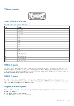
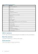
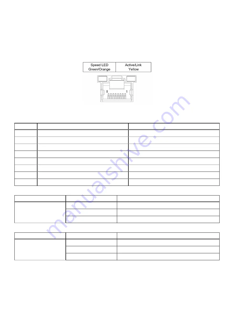
Figure 13. Ethernet port and LEDs
Table 10. Ethernet port pin definitions
Pin #
10BASE-T/100BASE-TX
1000BASE-T
1
TX+
2
TX–
LAN_TX0–
3
RX+
4
-
5
-
LAN_TX2–
6
RX–
LAN_TX1–
7
-
8
-
LAN_TX3–
Table 11. Active/Link LED indicators
LED Color
Status
Description
Yellow
OFF
Ethernet port is disconnected.
ON
Ethernet port is connected with no activity.
Flashing
Ethernet port is connected and active.
Table 12. Speed LED indicators
LED Color
Status
Description
Green/Orange
OFF
10 Mbps
Green
100 Mbps
Orange
1000 Mbps
18
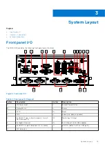
System Layout
Summary of Contents for EGW-5200
Page 1: ...Dell EMC Edge Gateway 5200 User s Guide January 2022 Rev A01 ...
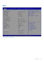
Page 31: ...Main Figure 27 BIOS screen Main tab BIOS Setup 31 ...
Page 32: ...Advanced Figure 28 BIOS screen Advanced tab 32 BIOS Setup ...
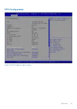
Page 33: ...CPU Configuration Figure 29 CPU Configuration top of screen BIOS Setup 33 ...
Page 47: ...NVMe Configuration Figure 41 NVMe Configuration BIOS Setup 47 ...
Page 51: ...Memory Configuration Figure 45 Memory Configuration BIOS Setup 51 ...
Page 54: ...PCH IO Configuration Figure 48 PCH IO Configuration 54 BIOS Setup ...
Page 56: ...Security Configuration Figure 50 Security Configuration 56 BIOS Setup ...
Page 57: ...M 2 Device Configuration Figure 51 M 2 Device Configuration BIOS Setup 57 ...
Page 58: ...Security Figure 52 BIOS screen Security tab 58 BIOS Setup ...
Page 64: ...Save and Exit Figure 57 BIOS screen Save and Exit tab 64 BIOS Setup ...
Page 65: ...Event logs Figure 58 BIOS screen Event logs tab BIOS Setup 65 ...