background image

Back to Contents Page


System Codes and Messages: Dell™ Dimension™ L Series

 Reference 

Diagnostic Codes 

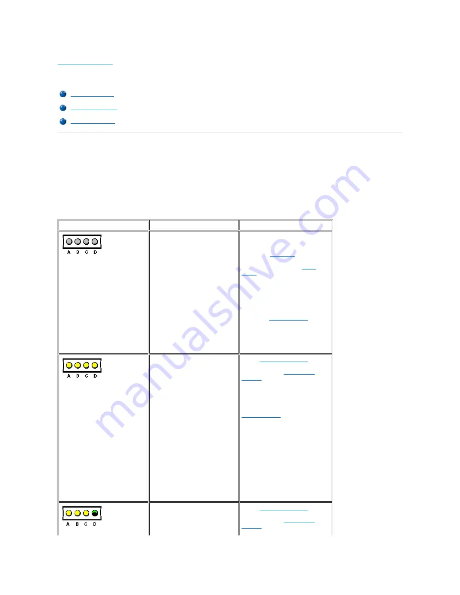
Your system is equipped with four diagnostic code indicators, which are labeled "A," "B," "C," and "D" on the back of the computer. Each of the 
four indicators can be yellow, green, or off, as shown in Table 1. When the computer is turned on or restarted and the system is functioning 
normally, the indicators flash during power-on self-test (POST). After the system starts, the indicators remain green to signify normal system 
operation. 

If a malfunction is detected and the computer fails to start, the indicators display a code that identifies the problem. Write down the diagnostic code 
displayed and look it up in Table 1. 

Table 1. Diagnostic Codes


Diagnostic Codes

POST Beep Codes

System Messages

Diagnostic Code

Definition

Corrective Action

Power up default.

Make sure that the system is 
connected to a known working 
electrical outlet, and then check 
whether the 

front-panel

 power 

indicator is on or off. If the power 

indicator is off, check the 

power 

supply

. If the problem persists, see 

Chapter 7, "Getting Help," of the 

Dell 

Dimension L Series Reference and 
Troubleshooting Guide 

for 

instructions on obtaining technical 
assistance.

Remove all 

expansion cards

. If the 

system still does not start, see 
Chapter 7, "Getting Help," of the 

Reference and Troubleshooting 
Guide 

for instructions on obtaining 

technical assistance. 

System board is receiving power, 
but the BIOS is not executing.

Set the 

configuration jumper

 to 

Maintenance mode, and restart the 
system. Enter the 

system setup 

program

 and ensure that the 

processor speed is set correctly. Exit 
and save the setting. Turn off the 
computer, reset the configuration 
jumper to Normal mode, and then 
restart the system. Remove all 

expansion cards

 and restart the 

system to determine if a resource 
conflict exists. If a conflict exists, 
resolve the conflict as described in 
"Resolving Software and Hardware 
Incompatibilities" in Chapter 5 of the 

Reference and Troubleshooting 
Guide

If the problem persists, see Chapter 
7, "Getting Help," of the 

Reference 

and Troubleshooting Guide 

for 

instructions on obtaining technical 
assistance. 

Recovery mode from BIOS failure.

Set the 

configuration jumper

 to 

Maintenance mode, and restart the 
system. Enter the 

system setup 

program

 and ensure that the 

processor speed is set correctly. Exit 

Summary of Contents for DimensionL Series

Page 1: ...istered trademarks and Celeron is a trademark of Intel Corporation VESA is a registered trademark of Video Electronics Standards Association Adobe is a trademark of Adobe Systems Incorporated which may be registered in certain jurisdictions Other trademarks and trade names may be used in this document to refer to either the entities claiming the marks and names or their products Dell Computer Corp...

Page 2: ...ee Chapter 7 Getting Help of the Dell Dimension L Series Reference and Troubleshooting Guide for instructions on obtaining technical assistance Remove all expansion cards If the system still does not start see Chapter 7 Getting Help of the Reference and Troubleshooting Guide for instructions on obtaining technical assistance System board is receiving power but the BIOS is not executing Set the con...

Page 3: ...sts resolve the conflict as described in Resolving Software and Hardware Incompatibilities in Chapter 5 of the Reference and Troubleshooting Guide If the problem persists see Chapter 7 Getting Help of the Reference and Troubleshooting Guide for instructions on obtaining technical assistance Video controller failed to initialize or respond If the problem persists see Chapter 7 Getting Help of the R...

Page 4: ...Optional ROM checksum error See Chapter 7 Getting Help of the Reference and Troubleshooting Guide for instructions on obtaining technical assistance 10 CMOS memory error See Chapter 7 Getting Help of the Reference and Troubleshooting Guide for instructions on obtaining technical assistance 11 BIOS checksum error See Chapter 7 Getting Help of the Reference and Troubleshooting Guide for instructions...

Page 5: ...interface cable at both ends INTR1 Error INTR2 Error Interrupt channel on the system board failed the POST The keyboard or system board may need to be replaced Invalid Boot Diskette The operating system cannot be located on drive A or drive C Enter the system setup program and confirm that drive A or drive C is properly identified KB Interface Error An error occurred with the keyboard connector Th...

Page 6: ...ssed 2 Power Turns the computer on and off Lights up when the computer is on Press and hold for 4 seconds to shut down 3 Hard disk drive access indicator Lights up when a hard disk drive is being accessed 1 Voltage selection switch Selects the operating voltage for the computer 2 Diagnostic code indicators 4 If a malfunction is detected and the computer fails to start the indicators display a code...

Page 7: ...y unless otherwise indicated to perform a single function Example Ctrl Alt Enter l Commands presented in lowercase bold are for reference purposes only and are not intended to be typed when referenced Example Use the format command to In contrast commands presented in the Courier New font are part of an instruction and intended to be typed Example Type format a to format the diskette in drive A l ...

Page 8: ......

Page 9: ... Run 4 Type regsvr32 popup ocx and then press Enter 5 Click OK when the installation is complete 6 Right click the following link to the Help file LSerHelp chm 7 Click Save Target As in Microsoft Internet Explorer or Save Link As in Netscape Navigator and specify a location on your hard disk drive Viewing the Help File To view the Help file perform the following steps 1 Click the Start button on t...

Page 10: ... on how to reinstall those drivers see the device s documentation On some computers a device s documentation can be found by double clicking the Dell Documents icon on the Windows desktop clicking System Information and then clicking System Documentation On other computers the documentation can be found by clicking the Start button on the Windows desktop pointing to Programs pointing to User s Gui...

Page 11: ...erface controller NIC cards that might be installed on your system For instructions on how to reinstall those drivers see the device s documentation On some computers a device s documentation can be found by double clicking the Dell Documents icon on the Windows desktop clicking System Information and then clicking System Documentation On other computers the documentation can be found by clicking ...

Page 12: ...ist click the drivers folder An alert message appears informing you that only knowledgeable users should install drivers 6 Click OK to continue 7 In the All Folders list click the win98 or winnt folder 8 In the Description list click Dimension L Series Intel Security Driver 9 Click the only file that appears in the All Files list The file is named nnnnnnnn exe where nnnnnnnn is an eight digit part...

Page 13: ...anguage 5 Select the language of your choice and click OK 6 In the All Folders list click the drivers folder An alert message appears informing you that only knowledgeable users should install drivers 7 Click OK to continue 8 In the All Folders list click the win98 folder 9 In the Description list click Dimension L Series Intel 810 Video Driver 10 Click the only file that appears in the All Files ...

Page 14: ... systems Creative Labs Audio Driver for Windows 98 To reinstall the Creative Labs audio driver on systems running Windows 98 perform the following steps 1 Start the Windows 98 operating system 2 Insert the Dell Dimension ResourceCD into the CD ROM or DVD ROM drive The Dell Dimension ResourceCD screen appears 3 Click the right arrow button The first time that you use the Dell Dimension ResourceCD y...

Page 15: ...installed the audio drivers are automatically installed If you need to reinstall the audio drivers you must reinstall Windows 2000 Intel 82559 Fast Ethernet LAN on Motherboard NIC Driver Dell installed the Intel 82559 Fast Ethernet LAN on Motherboard NIC driver on your hard disk drive No further installation or configuration is needed If you ever need to reinstall this driver see the appropriate p...

Page 16: ...k OK 8 From the Select OEM Options window select Intel PRO Adapter and click OK to begin the driver installation 9 From the Network window click the Adapters tab and verify that the Intel 82559 Fast Ethernet LAN on Motherboard was installed and then click Close 10 When prompted to restart the computer remove the Dell Dimension ResourceCD from the CD ROM or DVD ROM drive and then click Yes Intel 82...

Page 17: ...ply DIMMs Bezel Heat Sink 3 5 Inch Front Panel Insert Microprocessor Upper 3 5 Inch Drive Battery Lower 3 5 Inch Diskette Drive System Board 5 25 Inch Drive CAUTION FOR YOUR PERSONAL SAFETY AND PROTECTION OF THE EQUIPMENT Before you start to work on the system perform the following steps in the sequence listed 1 Turn off your computer and all devices 2 Ground yourself by touching an unpainted meta...

Page 18: ...r extra parts including screws are left inside the computer 3 Place the chassis upright with the front facing you Align the computer cover so that its bottom hooks fit in the chassis curves 4 Lift up the cover making sure to keep the bottom hooks aligned with the curves in the chassis 5 Gently squeeze the right and left sides of the computer together until the cover clicks into position Rotating t...

Page 19: ...n you rotate the power supply back into the chassis gently lift the cable retainer and hold the drive cables out of the way 5 Rotate the power supply into position until its release latch clicks 6 Wrap the drive cables along the top of the latch in the retainers as shown in the following figure Bezel 1 Release latch 2 Power supply 3 Cable retainer 1 Cable retainer 2 Drive power cables 3 Power supp...

Page 20: ...the chassis 4 To replace the bezel fit the two bezel retaining hooks into their corresponding slots on the chassis Rotate the bezel toward the chassis until the bezel latches into position 3 5 Inch Front Panel Insert To remove a 3 5 inch insert perform the following steps 1 Remove the bezel 2 From the back of the bezel press the release tab to the side 3 Rotate the insert toward you and remove it ...

Page 21: ...t side of the drive and R for the right side of the drive 7 Slide the drive assembly into the drive bay 8 Connect the power supply cable and drive interface cables to the drive Lower 3 5 Inch Diskette Drive To remove the 3 5 inch diskette drive from the lower bay perform the following steps 1 Remove the bezel 2 Rotate the power supply away from the system board 3 While holding the power supply pla...

Page 22: ...upply away from the system board 3 While holding the power supply place the computer in the upright position 4 Remove the two screws securing the hard disk drive to the front of the chassis 5 Release the clip that secures the drive to the chassis and rotate the drive out of the chassis 6 Disconnect any cables attached to the drive 7 Remove the existing drive from the bay To reinstall the primary h...

Page 23: ...board 4 Disconnect the DC power cables from the POWER and OPTIONAL POWER connectors on the system board 5 Disconnect the DC power cables from all the drives 6 Press the power supply retaining clips and lift the power supply and fan assembly out of the chassis Control Panel To remove the control panel perform the following steps 1 Remove the bezel 2 Disconnect the control panel from the system boar...

Page 24: ...ing steps 1 Remove the computer cover 2 Rotate the power supply 3 Disconnect any cables connected to the card 4 Remove the screw from the card mounting bracket 5 Grasp the card by its top corners and ease it out of its connector 6 If you are removing the card permanently install a metal filler bracket over the empty card slot opening in the chassis DIMMs To remove a dual in line memory module DIMM...

Page 25: ...eding figure To remove and replace the microprocessor and heat sink perform the following steps 1 Remove the computer cover 2 Rotate the power supply 3 Locate the microprocessor socket on the system board 4 Release the metal clip that secures the heat sink and fan assembly to the microprocessor socket Then remove the heat sink and fan assembly from the microprocessor chip 5 Disconnect the fan from...

Page 26: ... any of the pins when you remove the microprocessor chip from its socket Bending the pins can permanently damage the microprocessor chip Your microprocessor socket is a zero insertion force ZIF socket with a lever type handle that secures the chip in or releases it from the socket 1 To remove the chip pull the microprocessor socket release lever out to unlock it and then straight up until the chip...

Page 27: ...t snaps into place securing the chip Battery To remove the 3 volt V CR2032 coin cell battery perform the following steps 1 Make a copy of the screens in the system setup program Enter the system setup program and print by pressing the Print Screen key or copy the system configuration information from the system setup screens 2 Remove the computer cover 3 Rotate the power supply 4 Pry the battery o...

Page 28: ...O gasket When properly aligned the board connectors slide into the I O gasket as you lower the board into position in the chassis and reseat it on the standoffs Lock the board in place with the system board retaining clip After you install the replacement system board replace the microprocessor the heat sink the DIMMs and the expansion cards that you removed from the old system board To configure ...

Page 29: ...7 Re enter the system setup program and reset the system configuration information Back to Contents Page ...

Page 30: ... 600 633 667 700 or 733 MHz internally and 66 MHz externally or 700 or 800 MHz internally and 100 MHz externally Dimension Lxxxc Intel Celeron processor that runs at 400 433 466 or 500 MHz internally and 66 MHz externally NOTE Microprocessor offerings vary by country L1 cache 32 KB instruction and data cache L2 cache Pentium III processor 256 KB Advanced Transfer Cache that resides in the processo...

Page 31: ...hree SPD revision 1 2 Buffering unbuffered Voltage 3 3 V Data bus width 64 bits BIOS address F0000h 1 Video memory uses 1 or 2 MB of system memory RAM Total RAM reported is 1 or 2 MB less than RAM installed Drives Externally accessible one 5 25 inch bay and two 3 5 inch bays Internally accessible one bay for 1 inch high EIDE hard disk drive Ports Externally accessible Serial DTE 9 pin connector 16...

Page 32: ... controller2 Creative Sound Blaster Audio PCI chip with 64 voice wavetable synthesis 2 Present only on systems with integrated audio and network capabilities Network NIC2 Intel Pro 10 100 Mbps 82559 chip 2 Present only on systems with integrated audio and network capabilities Power DC power supply Wattage 145 W Heat dissipation 700 BTU fully loaded system without monitor Voltage switch selectable ...

Page 33: ...aximum operating altitude is 914 m 3000 ft Regulatory Notices FCC U S only Class B IC Notice Canada only Class B CE Notice Class B VCCI Notice Japan only Class B NOM O24 Information Mexico only IRQ Line System Resource IRQ Line System Resource IRQ0 System timer IRQ8 RTC IRQ1 Keyboard buffer IRQ9 Available IRQ2 Enables IRQ8 through IRQ15 IRQ10 Available IRQ3 Available4 IRQ11 Available IRQ4 Serial p...

Page 34: ... options contain settings or values You can change those that are enclosed in brackets Values that are grayed out contain status information reported by the system l The box on the right side of each screen displays help information for the option with a currently highlighted field l The bottom right area lists keys and their functions for the currently displayed screen The menu bar provides acces...

Page 35: ...for the system Total Memory Displays the total system memory Memory Bank 0 Displays the memory installed in memory bank 0 Memory Bank 1 Displays the memory installed in memory bank 1 Processor Serial Number NOTE This option is available only on Dell Dimension Lxxxr computers Displays the serial number of the processor when set to Enabled Disabled default turns off this feature System Time Resets t...

Page 36: ...ices from the operating system or from the system BIOS Leave this option set to No so that the BIOS handles all Plug and Play operations NOTE Be sure that this option is set to No before running Dell Diagnostics Otherwise some diagnostics may incorrectly report failures Reset Config Data Permits resetting of the Plug and Play configuration data to default values Yes resets the data No default reta...

Page 37: ...ption to Disabled if you are using a network card instead of the integrated NIC or if the resources used by the controller are needed Legacy USB Support Set to Disabled if legacy USB support is not desired Auto default and Enabled allow support for legacy USB IRQ5 Reserved default indicates that the IRQ is reserved for use by legacy systems Available indicates that a specific IRQ is available on t...

Page 38: ...ers Determines the number of sectors per block during multiple sector transfers If Type is set to User set Multi Sector Transfers to 2 Sectors 4 Sectors 8 Sectors 16 Sectors or Disabled turns off the feature PIO Mode Determines the method of moving data to and from the EIDE drive Options include PIO modes 0 1 2 3 and 4 The PIO modes can improve the performance of a hard disk drive The higher the P...

Page 39: ... Function Event Log Displays the space available for the event log Event Log Validity Displays the validity of the event log View Event Log Press Enter to view the event log Clear All Event Logs Clears all event logs when the system restarts if set to Yes Retains the event log information if set to No default Event Logging Enables or disables event logging Mark Events As Read Press Enter and then ...

Page 40: ...splays the Dell logo Disabled displays the normal POST messages Quick Boot When set to Enabled this option shortens the POST by eliminating some tests If set to Disabled default all POST tests occur Restore on AC Power Loss Determines what state the system enters when AC power is restored after a power loss Settings are as follows l Last State default System returns to the state it was in when pow...

Page 41: ...through 4th IDE HDD l Floppy l ARMD FDD l ARMD HDD l ATAPI CD ROM l SCSI l Network Where SCSI or Network is the name of the installed device 2nd Boot Device Determines which device the system tries to boot from if it cannot boot from the device selected for 1st Boot Device Settings for this option are the same as those for 1st Boot Device except for NETWORK 3rd Boot Device Determines which device ...

Page 42: ...de exits the system setup program and restarts the system Exit Discarding Changes Discards any changes you have made exits the system setup program and restarts the system Load Setup Defaults Discards any changes you have made and reverts all options to their defaults but does not exit the system setup program Load Custom Defaults Loads any settings saved using the Save Custom Defaults option Pres...

Page 43: ...tion Jumper 1 Bezel release 2 5 25 inch drive bay 3 3 5 inch drive bays 4 Hard disk drive 5 Power supply 6 AC power connector 7 I O panel 8 Security cable slot 9 Release latch and padlock ring 1 Mouse connector 2 Network connector 3 Parallel port connector 4 MIDI game port connector 5 Keyboard connector 6 USB connectors 2 7 Video connector 8 Serial port connector 9 Diagnostic code indicators 4 10 ...

Page 44: ...9A1 27 Keyboard connector KEYBD 13 Configuration jumper J7A1 28 Auxiliary line in audio connector for systems with integrated audio natural color AUX IN 14 Power indicator 29 Modem audio cable connector for using integrated audio system as a speaker phone green color TELEPHONY 15 PCI expansion card connectors natural color PCIn NOTE The red dot in the jumper denotes pin 1 Jumper Setting Jumper Des...

Page 45: ...Disabling a Forgotten Password in Appendix B of the Dell Dimension L Series Reference and Troubleshooting Guide NOTE The power supply produces DC voltages only under its loaded condition The DC power cable connectors must be connected to their corresponding power input connectors on the system board or drives to measure these voltages Voltage Range Maximum Output Current Notes 3 3 VDC 3 14 to 3 47...

Page 46: ...on DC Power Connector P2 DC Power Connector P3 DC Power Connectors P4 P5 and P6 Back to Contents Page 1 5 VDC red 11 PSON 2 brown 2 Common black 12 Common black 3 5 VDC red 13 Common black 4 Common black 14 Common black 5 PWRGOOD1 orange 15 5 VDC white 6 5 VFP purple 16 5 VDC red 7 12 VDC yellow 17 5 VDC red 8 12 VDC blue 18 5 VDC red 9 Common black 19 Not connected 10 Common black 20 5 VDC red 1 ...

Reviews: