

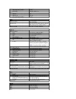

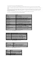


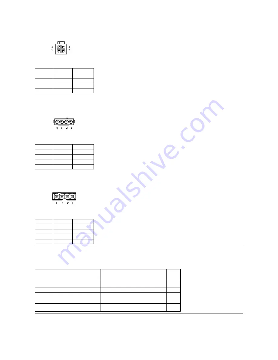
DC Power Connectors P3, P5, P6, P8, and P9
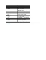
DC Power Connector P7
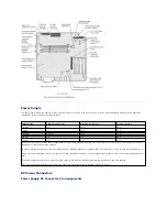
IDE Interface Cable Connections for Dell-Installed Drives
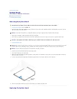
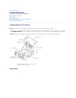
Placement of Dell-Installed Cards
Pin Number Signal Name 18-AWG Wire
1
COM
Black
2
COM
Black
3
+12 VDC
Yellow
4
+12 VDC
Yellow
Pin Number Signal Name 18-AWG Wire
1
+12 VCD
Yellow
2
COM
Black
3
COM
Black
4
+5 VDC
Red
Pin Number Signal Name 22-AWG Wire
1
+5 VCD
Red
2
COM
Black
3
COM
Black
4
+12 VDC
Yellow
IDE Channel
Connector Location
Dell-
Installed
Drive
Primary IDE master
End connector on PRI IDE connector cable
Hard
drive
Primary IDE slave
Middle connector on PRI IDE connector cable
Zip drive
Secondary IDE master
End connector on SEC IDE connector cable
CD or
DVD
drive
Secondary IDE slave
Middle connector on SEC IDE connector cable
CD-RW
drive
Summary of Contents for Dimension 8300 Series
Page 6: ...Back to Contents Page ...
Page 42: ...Back to Contents Page ...


