background image

4.

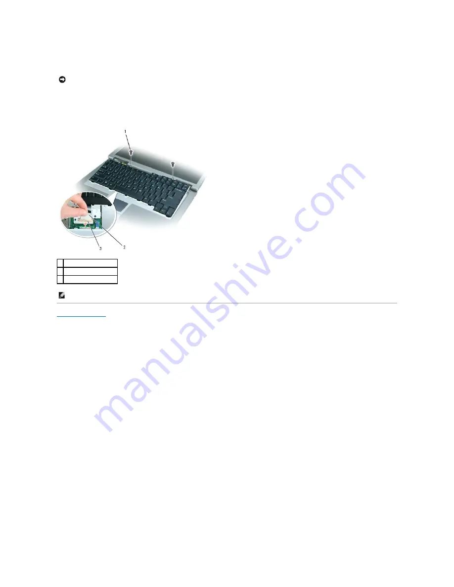
Remove the keyboard:  
 

a.


Remove the two M2.5 x 5-mm screws across the top of the keyboard.  


b.


Slide the keyboard towards the display until it is free of the palm rest and hold it slightly above the computer, to allow access to the keyboard 

connector.  
 

c.


Pull the keyboard connector tab to disconnect the keyboard connector from the system board.  


d.


Set the keyboard aside.  


Back to Contents Page


NOTICE: 

The keycaps on the keyboard are fragile, easily dislodged, and time-consuming to replace. Be careful when removing and handling the 

keyboard.

1  M2.5 x 5-mm screws (2) 

2  keyboard connector tab 

3  keyboard connector 


NOTE: 

When you replace the keyboard, ensure that the keyboard tabs are completely secured beneath the palm rest to avoid scratching it.

Summary of Contents for 510D

Page 1: ...to either the entities claiming the marks and names or their products Dell Inc disclaims any proprietary interest in trademarks and trade names other than its own Model PP10L April 2005 Rev A00 Before You Begin System Components Memory Module Modem Mini PCI Card and Optical Devices Hard Drive Internal Card With Bluetooth Wireless Technology Keyboard Coin Cell Battery Microprocessor Thermal Cooling...

Page 2: ...evices do not automatically turn off when you shut down your operating system press and hold the power button for 4 seconds Before Working Inside Your Computer Use the following safety guidelines to help protect your computer from potential damage and to help ensure your own personal safety NOTICE To avoid losing data save and close any open files and exit any open programs before you turn off you...

Page 3: ...mputer and then remove the battery from the battery bay 9 Remove any installed memory modules modems Mini PCI cards internal cards with Bluetooth wireless technology backup batteries and optical devices 10 Remove the hard drive Computer Orientation NOTICE To disconnect a network cable first unplug the cable from your computer and then unplug it from the network port or device NOTICE To prevent dam...

Page 4: ...s a guide to keep track of the screws The placemat provides the number of screws and their sizes 1 back 2 right 3 front 4 left Optical Device optional security screw 1 each Hard Drive 2 each Keyboard 2 each Modem 1 each Hard Drive Carrier 2 each Display Bezel display bumpers 5 each 6 each ...

Page 5: ...Back to Contents Page Display Panel 8 each Display Assembly 4 each Display Latch 1 each Palm Rest 4 each 14 each Speakers 1 each Fan 2 each System Board 2 each 4 each ...

Page 6: ...uter automatically reboots 5 Remove the flash BIOS update program floppy or CD from the drive Back to Contents Page NOTICE To avoid damaging the system board ensure you are connected to a known good electrical outlet and that you do not interrupt the BIOS flash process Loss of power or an interruption during the BIOS flash process can cause damage to the system board NOTE If you wait too long and ...

Page 7: ...ireless technology 2 Ensure that the card cable is routed under the tab CAUTION Before performing the following procedures read the safety instructions in your Product Information Guide NOTICE To prevent damage to components inside your computer discharge static electricity from your body before you touch any of your computer s electronic components You can do so by touching an unpainted metal sur...

Page 8: ...3 Connect the card cable 4 Replace the hard drive Back to Contents Page 1 cable 2 tab ...

Page 9: ... computer base 5 Disconnect the coin cell battery cable connector from the battery connector Back to Contents Page CAUTION Before working inside your Dell computer read the safety instructions in your Product Information Guide NOTICE To prevent damage to components inside your computer discharge static electricity from your body before you touch any of your computer s electronic components You can...

Page 10: ...o not touch the processor die Press and hold the microprocessor down on the substrate on which the die is mounted while turning the cam screw to prevent intermittent contact between the cam screw and microprocessor NOTICE To avoid damage to the microprocessor hold the screwdriver so that it is perpendicular to the microprocessor when turning the cam screw NOTICE To ensure maximum cooling for the m...

Page 11: ...ckwise to secure the microprocessor module to the system board 3 Replace the parts that you removed in Removing the Microprocessor Module Back to Contents Page NOTICE A microprocessor module that is not properly seated can result in an intermittent connection or permanent damage to the microprocessor and ZIF socket NOTE The pin 1 corner of the microprocessor module has a triangle that aligns with ...

Page 12: ...m beneath the tab on the palm rest 7 Release the two antenna cables from the two antenna securing clips 8 Disconnect one antenna cable from the display by holding the two gold antenna connectors and gently pulling them apart Then disconnect the other antenna cable The gold antenna connectors on each cable are keyed to ensure that they are correctly reconnected CAUTION Before performing the followi...

Page 13: ...ble 2 display cable connector on system board 3 antenna cables 2 4 antenna securing clips 2 1 M2 5 x 5 mm screws 4 CAUTION Before performing the following procedures read the safety instructions in your Product Information Guide NOTICE To prevent damage to components inside your computer discharge static electricity from your body before you touch any of your computer s electronic components You c...

Page 14: ...ng to Work Inside Your Computer 2 Remove the keyboard 3 Remove the display bezel 4 Remove the eight M2 x 5 mm screws from the display panel 1 display bumper 4 M2 x 5 mm screws 6 2 support bracket 5 display bumpers 4 3 display panel 6 display bezel NOTICE Carefully separate the bezel from the top cover to avoid damage to the bezel CAUTION Before performing the following procedures read the safety i...

Page 15: ...e the keyboard 3 Remove the display assembly 4 Remove the display bezel 1 display panel 2 top cover 3 M2 x 5 mm screws 8 1 top flex cable connector 2 display connector 3 bottom flex cable connector with pull tab CAUTION Before performing the following procedures read the safety instructions in your Product Information Guide NOTICE To prevent damage to components inside your computer discharge stat...

Page 16: ...nd then remove the display latch Back to Contents Page NOTICE A strip of copper foil may be present beneath the support bracket on some systems ensure that you do not tear this foil while removing the bracket NOTE Ensure that the support bracket is upright when you replace the display latch 1 top cover 2 M2 x 4 mm screw 1 3 support bracket 4 display latch ...

Page 17: ...tem board 6 Remove the two M2 5 x 8 mm screws from the fan and pull the fan away from the system board CAUTION Before performing the following procedures read the safety instructions in your Product Information Guide NOTICE To prevent damage to components inside your computer discharge static electricity from your body before you touch any of your computer s electronic components You can do so by ...

Page 18: ...Back to Contents Page 4 system board connector ...

Page 19: ... drive from its carrier and attach the carrier to the new hard drive CAUTION If you remove the hard drive from the computer when the drive is hot do not touch the metal housing of the hard drive CAUTION Before working inside your computer read the safety instructions in your Product Information Guide NOTICE To prevent data loss shut down your computer before removing the hard drive Do not remove t...

Page 20: ... pry the carrier open near the back of the carrier 3 Lift the hard drive out of the carrier Back to Contents Page NOTICE Use firm and even pressure to slide the drive into place If you force the hard drive into place using excessive force you may damage the connector CAUTION If you remove the hard drive from the computer when the drive is hot do not touch the metal housing of the hard drive CAUTIO...

Page 21: ...omputer use a plastic scribe to pry up the center control cover Lift it away from the computer and lay it aside CAUTION Before performing the following procedures read the safety instructions in your Product Information Guide NOTICE To prevent damage to components inside your computer discharge static electricity from your body before you touch any of your computer s electronic components You can ...

Page 22: ... connector tab to disconnect the keyboard connector from the system board d Set the keyboard aside Back to Contents Page NOTICE The keycaps on the keyboard are fragile easily dislodged and time consuming to replace Be careful when removing and handling the keyboard 1 M2 5 x 5 mm screws 2 2 keyboard connector tab 3 keyboard connector NOTE When you replace the keyboard ensure that the keyboard tabs ...

Page 23: ... base latch straight up and away from the computer base Back to Contents Page CAUTION Before performing the following procedures read the safety instructions in your Product Information Guide NOTICE To prevent damage to components inside your computer discharge static electricity from your body before you touch any of your computer s electronic components You can do so by touching an unpainted met...

Page 24: ...lm rest 6 Remove the M2 5 x 5 mm screw labeled P from the metal shield CAUTION Before performing the following procedures read the safety instructions in your Product Information Guide NOTICE To prevent damage to components inside your computer discharge static electricity from your body before you touch any of your computer s electronic components You can do so by touching an unpainted metal surf...

Page 25: ...pressing down on the back of the computer base Back to Contents Page 1 M2 5 x 5 mm screws labeled P 4 1 touch pad connector 2 system board connector NOTICE Carefully separate the palm rest from the computer base to avoid damage to the palm rest NOTE When you reinstall the palm rest attach the right side of the palm rest first and ensure that the modem ends of the antennae cables are visible in the...

Page 26: ... Connector S Video TV Out Connector Serial Connector IEEE 1394 Connector USB Connector Video Connector Parallel Connector Pin Signal 1 USB5V 2 USBP 3 USBP 4 GND Pin Signal Pin Signal 1 CRT_R 9 5V 2 CRT_G 10 GND 3 CRT_B 11 MONITOR_DETECT 4 NC 12 DDC_DATA 5 GND 13 CRT_HS 6 GND 14 CRT_VS 7 GND 15 DDC_CLK 8 GND Pin Signal Pin Signal ...

Page 27: ... 11 BUSY 3 PD1 12 PE 4 PD2 13 SLCT 5 PD3 14 AFD 3M 6 PD4 15 ERROR 7 PD5 16 INIT 8 PD6 17 SLIN 9 PD7 18 25 GND S Video Pin Signal 1 GND 2 GND 3 DLUMA L 4 DCRMA L Composite Video Pin Signal 5 NC 6 DCMPS L 7 GND Pin Signal Pin Signal 1 DCD 6 DSR 2 RXDA 7 RTS 3 TXDA 8 CTS 4 DTR 9 RI 5 GND ...

Page 28: ...Back to Contents Page Pin Signal 1 TPB 2 TPB 3 TPA 4 TPA ...

Page 29: ...read the safety instructions in your Product Information Guide NOTICE To prevent damage to components inside your computer discharge static electricity from your body before you touch any of your computer s electronic components You can do so by touching an unpainted metal surface NOTICE To avoid damage to the speaker cable be sure to re route it through both securing clips When inserting it back ...

Page 30: ...thermal cooling assembly 4 Remove the microprocessor 5 Remove the speakers 6 Remove the two M2 5 x 5 mm screws labeled B 7 Turn the computer upside down and remove the four M2 x 3 mm screws labeled B that secure the system board to the computer base CAUTION Before performing the following procedures read the safety instructions in your Product Information Guide NOTICE Disconnect the power supply a...

Page 31: ...ppy disk or CD that accompanied the replacement system board into the appropriate drive and follow the instructions that appear on the screen Back to Contents Page 1 M2 x 3 mm screws labeled B 4 1 system board securing clips 2 NOTICE Before turning on the computer replace all screws and ensure that no stray screws remain inside the computer Failure to do so may result in damage to the computer NOT...

Page 32: ... warranty NOTICE Unless otherwise noted each procedure in this document assumes that a part can be replaced or if purchased separately installed by performing the removal procedure in reverse order 1 display assembly 8 microprocessor 2 center control cover 9 optical device 3 keyboard 10 battery 4 palm rest with touch pad 11 computer base 5 microprocessor thermal cooling assembly 12 hard drive 6 gr...

Page 33: ...by holding the two gold antenna connectors and gently pulling them apart Then disconnect the other antenna cable The gold antenna connectors on each cable are keyed to ensure that they are correctly reconnected 8 In consecutive order loosen the four captive screws labeled 1 through 4 that secure the microprocessor thermal cooling assembly to the system board CAUTION Before performing the following...

Page 34: ...oling assembly underneath the palm rest and then place the assembly over the microprocessor 2 Tighten the four captive screws labeled 1 through 4 in consecutive order NOTICE Ensure that you do not trap any cables beneath the microprocessor thermal cooling assembly when you replace it NOTICE While tightening the screws ensure that the cooler plate is no higher than the screw heads 1 incorrectly ins...

Page 35: ...nd place it between its routing clips 4 Attach the display cable to the display panel connector on the system board 5 Reconnect the two antenna cables and then secure them into the two antenna securing clips Back to Contents Page 2 correctly installed heat sink ...

Page 36: ...of Microsoft Corporation Bluetooth is a trademark owned by Bluetooth SIG Inc and is used by Dell Inc under license Other trademarks and trade names may be used in this document to refer to either the entities claiming the marks and names or their products Dell Inc disclaims any proprietary interest in trademarks and trade names other than its own Model PP10L April 2005 Rev A00 Back to Contents Pag...

Page 37: ...y module connector until the module pops up b Remove the module from the connector CAUTION Before working inside your Dell computer read the safety instructions in your Product Information Guide NOTICE To prevent damage to components inside your computer discharge static electricity from your body before you touch any of your computer s electronic components You can do so by touching an unpainted ...

Page 38: ...ab to disconnect the modem from the modem connector on the system board c Disconnect the modem cable from the modem NOTICE If you need to install memory modules in two connectors install a memory module in the connector labeled DIMM A before you install a module in the connector labeled DIMM B NOTICE Do not attempt to install non DDR2 memory modules in the connectors Installing incompatible memory...

Page 39: ... card b Release the Mini PCI card by spreading the securing clips until the card pops up slightly c Lift the Mini PCI card out of its connector NOTICE Do not press down on the left side of the modem side with the modem cable connection while installing it NOTICE If the memory module cover is difficult to close remove the module and reinstall it Forcing the cover to close may damage your computer C...

Page 40: ...nstalled in the module bay You can install an M2 x 3 mm optical device security screw in the bay if desired to make the device more difficult to remove NOTICE In the next step ensure that the antenna cables extend over the edge of the computer so that they are not trapped beneath the new Mini PCI card NOTICE The connectors are keyed for correct insertion do not force the connections 1 antenna cabl...

Page 41: ...s screwdriver to remove the optical device security screw from the bottom of the computer NOTE You do not need to install the device security screw unless you want to keep the module inside the computer for security purposes NOTICE To prevent damage to devices place them in a safe dry place when they are not installed in the computer Avoid pressing down on them or placing heavy objects on top of t...

Page 42: ... latch release so that the latch release pops out 6 Pull the device by the latch release to remove the device from the module bay 7 Push the new device into the bay until it clicks Back to Contents Page 1 M2 x 3 mm screw ...

Reviews: