background image

To disconnect:

1.

Turn off everything (unless instructed otherwise).

2.

Remove the power cords from the outlets.

3.

Remove the signal cables from the connectors.

4.

Remove all cables from the devices.

To connect:

1.

Turn off everything (unless instructed otherwise).

2.

Attach all cables to the devices.

3.

Attach the power cords to the outlets.

4.

Turn on the devices.

v

Sharp edges, corners and joints may be present in and around the system.
Use care when handling equipment to avoid cuts, scrapes and pinching.
(D005)

Heavy equipment - personal injury or equipment damage might result if
mishandled. (D006)

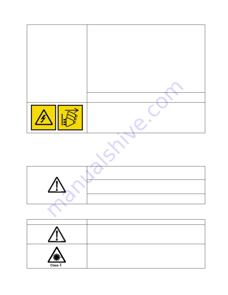
DANGER: Multiple power cords. The product might be equipped with
multiple power cords. To remove all hazardous voltages, disconnect all
power cords. (L003)

Caution notices

A caution notice calls attention to a situation that is potentially hazardous to people because of some
existing condition, or to a potentially dangerous situation that might develop because of some unsafe
practice.

The doors and covers to the product are to be closed at all times except for
service by trained service personnel. All covers must be replaced and doors
closed at the conclusion of the service operation. (C013)

This product is equipped with a 3-wire (two conductors and ground) power
cable and plug. Use this power cable with a properly grounded electrical
outlet to avoid electrical shock. (C018)

This assembly contains mechanical moving parts. Use care when servicing
this assembly. (C025)

A caution notice can be accompanied by one of several symbols:

If the symbol is...

It means...

A generally hazardous condition not represented by other safety symbols.

A hazardous condition due to the use of a laser in the product. Laser
symbols are always accompanied by the classification of the laser as defined
by the U. S. Department of Health and Human Services (for example, Class
I, Class II, and so forth).

Safety and environmental notices

xv

Summary of Contents for 3555-E3A

Page 1: ...Dell EMC ML3 Tape Library User s Guide ...

Page 2: ......

Page 3: ...nge without notice Copyright 2017 Dell Inc or its subsidiaries All rights reserved Dell EMC and other trademarks are trademarks of Dell Inc or its subsidiaries Other trademarks may be trademarks of their respective owners Printed December 2017 iii ...

Page 4: ...iv Dell EMC ML3 Tape Library User s Guide ...

Page 5: ...ttom modules 39 Installing modules in a rack 42 Installing a tabletop module 46 Aligning and connecting modules 46 Validating tape drive installation 49 Connecting cables 49 Powering on the library 51 The Initial Setup process 52 Initial configuration and customization 53 Labeling and loading tape cartridges 53 Verifying the installation 55 Advanced library configuration 55 Overview 56 Library par...

Page 6: ...gical Library information 140 Users account information 141 Appendix B LTO media 143 Data cartridges 143 Cartridge Read Write compatibility 144 WORM Write Once Read Many cartridges 144 WORM media 144 Data security on WORM media 145 WORM media errors 145 Cleaning cartridge 145 Labeling tape cartridges 145 Guidelines for bar code labels 147 Write Protect switch 147 Handling the cartridges 148 Provid...

Page 7: ... disengaged 48 47 Two modules in rack seen from the rear 48 48 Connected modules 49 49 Full height FC dual port 50 50 Half height FC single port 50 51 Half height SAS dual port 51 52 IP address selection 52 53 Open I O station seen from the left 54 54 Magazine pulled out 55 55 Management GUI main screen 60 56 Operator Panel main screen 62 57 Front panel LEDs 63 58 Internal view of the library 105 ...

Page 8: ...viii Dell EMC ML3 Tape Library User s Guide ...

Page 9: ...ht FC single port 50 25 Half height SAS dual port 51 26 Main screen elements 60 27 Navigation Dock 61 28 Status icons 61 29 Operator Panel menu tree 62 30 Front panel LEDs 63 31 Locating Management functions 63 32 Default settings 66 33 Magazine state 70 34 Resolving errors 73 35 Main error events 79 36 Warning events 86 37 Configuration Change events 93 38 Informational Events 94 39 Error codes o...

Page 10: ...x Dell EMC ML3 Tape Library User s Guide ...

Page 11: ...common library features Feature Minimum Firmware Levels Required LTO8 HH FH Tape Drives Library Firmware must be at 1 1 1 0 or greater to support the LTO8 tape drives Ensure that any host applications and device drivers are at the minimum level that is required to support LTO8 tape drives LTO6 HH FH and LTO7 HH FH Tape Drives Library Firmware must be at 1 1 0 1 A00 or greater to support the LTO6 a...

Page 12: ...and some services might not be available in your area To contact Dell for sales technical support or customer service issues follow the steps that are listed 1 Go to www Dell com support 2 Select your country from the drop down menu on the lower right corner of the page 3 For customized support a Enter your system Service Tag in the Enter your Service Tag field b Click Submit The support page that...

Page 13: ...t represent the severity of the safety condition The sections that follow define each type of safety notice and give examples Danger and Caution notices Danger notices A danger notice calls attention to a situation that is potentially lethal or extremely hazardous to people A lightning bolt symbol always accompanies a danger notice to represent a dangerous electrical condition xiii ...

Page 14: ...cord s connect power to this unit only with the Dell provided power cord Do not use the Dell provided power cord for any other product v Do not open or service any power supply assembly v Do not connect or disconnect any cables or perform installation maintenance or reconfiguration of this product during an electrical storm v The product might be equipped with multiple power cords To remove all ha...

Page 15: ...ause of some existing condition or to a potentially dangerous situation that might develop because of some unsafe practice The doors and covers to the product are to be closed at all times except for service by trained service personnel All covers must be replaced and doors closed at the conclusion of the service operation C013 This product is equipped with a 3 wire two conductors and ground power...

Page 16: ...ition due to the unit s susceptibility to electrostatic discharge Possible safety hazards Possible safety hazards to the operation of this product are Electrical An electrically charged frame can cause serious electrical shock Mechanical Hazards for example a safety cover missing are potentially harmful to people Chemical Do not use solvents cleaners or other chemicals that are not approved for us...

Page 17: ...nal parts 7 Check the top and bottom covers of the library for proper fit They must be in place and secure 8 Check the product label at the rear of the library to make sure that it matches the voltage at your outlet Rack safety The following general safety information must be used for all rack mounted devices DANGER Observe the following precautions when working on or around your IT rack system v ...

Page 18: ...r sliding drawers Do not pull out or install any drawer or feature if the rack stabilizer brackets are not attached to the rack Do not pull out more than one drawer at a time The rack might become unstable if you pull out more than one drawer at a time v For fixed drawers This drawer is a fixed drawer and must not be moved for servicing unless specified by the manufacturer Attempting to move the d...

Page 19: ... long distance relocation is required restore the rack cabinet to the configuration of the rack cabinet as you received it Pack the rack cabinet in the original packaging material or equivalent Also lower the leveling pads to raise the casters off the pallet and bolt the rack cabinet to the pallet R002 Power Cords For your safety Dell provides a power cord with a grounded attachment plug to use wi...

Page 20: ...xx Dell EMC ML3 Tape Library User s Guide ...

Page 21: ...lowing publications for more information v Dell EMC ML3 Tape Library Getting Started Guide provides unpacking and initial setup information v IBM Security Key Lifecycle Manager Knowledge Center which is located at http www 01 ibm com support knowledgecenter SSWPVP welcome lang en contains information to help you install configure and use the IBM Security Key Lifecycle Manager xxi ...

Page 22: ...xxii Dell EMC ML3 Tape Library User s Guide ...

Page 23: ...dule The library on the right shows the base module below the expansion module An individual library can consist of one base module and up to 6 expansion modules See Structure and supported library configurations on page 2 for supported configurations The library provides the following capabilities v New user interface for improved usability v Updated library communication system v I O magazines t...

Page 24: ...module except the lowest one can contain a 5 slot I O Station If a seven Module library has an I O Station for each module the maximum number of slots that can be configured as I O slots are 34 six modules with 5 slot I O Stations and the lowest module with a 4 slot I O Station Structure and supported library configurations Supported library configurations The library supports a single base module...

Page 25: ...y configuration 1 module library Base Module only Figure 4 Base Module 2 module library Base Module and 1 Expansion Module Figure 5 2 module library 3 module library Base Module and 2 Expansion Modules Figure 6 3 module library Figure 3 Expansion Module Overview 3 ...

Page 26: ...dule quantity Supported library configuration 4 module library Base Module and 3 Expansion Modules Figure 7 4 module library 5 module library Base Module and 4 Expansion Modules Figure 8 5 module library 4 Dell EMC ML3 Tape Library User s Guide ...

Page 27: ...Table 5 Library configurations continued Module quantity Supported library configuration 6 module library Base Module and 5 Expansion Modules Figure 9 6 Module library Overview 5 ...

Page 28: ...e 5 Library configurations continued Module quantity Supported library configuration 7 module library Base Module and 6 Expansion Modules Figure 10 7 module library 6 Dell EMC ML3 Tape Library User s Guide ...

Page 29: ...Module only 8 Error LED Amber Base Module only 9 USB port Base Module only 10 Operator Panel display Base Module only 11 Back Return button Base Module only 12 Navigation button Left Base Module only 13 Navigation button Up Base Module only 14 Navigation button Down Base Module only 15 Navigation button Right Base Module only 16 Enter button Base Module only 18 I O station Right magazine access ha...

Page 30: ... port B Base Module only secondary port for service usage 7 Ethernet port A Base Module only 8 Module alignment mechanism 9 Lower Expansion Module connection port 10 Unit Identifier LED Blue 11 Controller Error LED Yellow 13 Product Serial Number Tag location Physical and logical addresses of modules The library assigns each module a unique address to indicate its physical location shown in Figure...

Page 31: ...Magazines Each module contains two magazines holding up to 40 cartridges Figure 13 Physical numbering of modules Overview 9 ...

Page 32: ...ine 5 10 15 20 Drives 25 30 35 40 Front of the Right Magazine 4 9 14 19 24 29 34 39 3 8 13 18 23 28 33 38 2 7 12 17 22 27 32 37 1 6 11 16 21 26 31 36 Physical numbering of storage slots starts with the left magazine of the lowest module of your library In this module the numbers of the lowest row 1 6 11 16 21 26 31 36 are inaccessible to the accessor so Figure 14 Left magazine Figure 15 Right maga...

Page 33: ...r supply Table 9 Power supply LEDs Number Color Description 1 White AC power is connected but Module powered OFF 2 Green Module powered ON Bar code reader The high speed bar code reader is a part of the Base Module The bar code reader provides inventory feedback to the host application Operator Panel display and Management GUI by reading cartridge bar code labels The library stores the customized ...

Page 34: ... FC 1 8 Gbps FC 300 MB s LTO8 2U Full height Fibre Channel FC 2 8 Gbps FC 360 MB s The LTO tape drives communicate with the library through an internal Ethernet interface For enhanced performance the LTO tape drives include speed matching channel calibration and power management Speed matching dynamically adjusts the drive s normal native uncompressed data rate to the slower data rate of a server ...

Page 35: ...or details contact your ISV Figure 17 shows examples of methods for mixing LTO drive types in a logical library Drive sled back panels Six indicator LEDs are included on all drive sleds as shown in Figure 18 Table 11 Drive sled indicators Number Description 1 Port 0 activity 2 Port 1 activity 3 Library communication 4 Cartridge present 5 Power 6 Beacon UID Figure 17 Mixed drives in a logical libra...

Page 36: ... 3 Drive sled indicators see Figure 18 on page 13 Table 13 Half height FC single port Number Description 1 FC port 0 2 Drive sled indicators see Figure 18 on page 13 Figure 19 Half height SAS dual port Figure 20 Half height FC single port 14 Dell EMC ML3 Tape Library User s Guide ...

Page 37: ...13 Physical and logical addresses of drives The library assigns each tape drive a unique address to indicate its physical location shown in Figure 22 on page 16 The physical numbering is bottom up on all drives This information is shown on the Drives page of the Management GUI Figure 21 Full height FC dual port Overview 15 ...

Page 38: ...ed on other drives in the library See Library partitioning on page 57 Supported tape cartridges Within the library the supported LTO tape drives use the following cartridge types v LTO8 Data Cartridge v LTO8 WORM Data Cartridge v LTO7 Data Cartridge v LTO7 WORM Data Cartridge v LTO6 Data Cartridge v LTO6 WORM Data Cartridge v LTO5 Data Cartridge v LTO5 WORM Data Cartridge v LTO4 Data Cartridge v L...

Page 39: ...deactivated If issues occur with the library managed encryption on the library go to http www dell com tapeautomation for information on resolving the issue If your issue is not resolved contact Dell technical support 3 Configure library managed encryption on your library 4 Install the IBM SKLM application on the server that is designated as the key manager See IBM SKLM Knowledge Center for inform...

Page 40: ... path from the application to the intended target the library accessor or the drive mechanism the device driver transparently fails over to another path in response to a break in the active path Both types of failover include host side failover when configured with multiple HBA ports into a switch But CPF includes target side failover through the control paths that are enabled on more than one tap...

Page 41: ...provided server See Locating Management functions on page 63 v SNMP Support The Simple Network Management Protocol SNMP allows the library to send alerts over a LAN network to a monitoring server Occasionally the library might encounter situations that you want to know about These situations can be conditions that affect the library performance such as an open door that causes the library to stop ...

Page 42: ...ware firmware revisions and adapter cards Note The library requires an HBA with multiple LUN supports Also multiple LUN supports must be enabled on the host computer When multiple LUN supports are not enabled the host computer can see the tape drive but not the library Supported device drivers Dell provides device driver support for the LTO tape drives and the robotics in this library Dell maintai...

Page 43: ...l HTTP An embedded web server provides a management GUI for library management and query capabilities Secure Socket Layer SSL The tape library supports SSL a protocol for transmitting private documents through the internet Key Management Interoperability Protocol KMIP Used for communicating with the IBM Security Lifecycle Key Manager and other security key management software Simple Mail Transfer ...

Page 44: ...22 Dell EMC ML3 Tape Library User s Guide ...

Page 45: ...e responsible for the security of this library the cartridges that are contained within the library and shelf resident cartridges To prevent unauthorized access to data Dell recommends locating the library and all shelf resident cartridges in an area where access is controlled Onsite security measures You are also responsible for evaluating selecting and implementing security features administrati...

Page 46: ...overing of rack rails allowing for magazine opening clearance Electrical specifications Table 18 Electrical specifications Characteristic Specification Current 5 0 3 5 A Voltage 100 240 V 50 60 Hz Power 350 W Equipment environmental specifications Table 19 Equipment environmental specifications ML3 Operating environment Product power off Dry bulb temperature deg C Relative Humidity RH non condensi...

Page 47: ... of copper corrosion product thickness growth in Å month and the rate of weight gain assumes that Cu2S and Cu2O grow in equal proportions 3 The derivation of the equivalence between the rate of silver corrosion product thickness growth in Å month and the rate of weight gain assumes that Ag2S is the only corrosion product 4 The deliquescent relative humidity of particulate contamination is the rela...

Page 48: ...outh Korea Suriname Taiwan Trinidad Tobago Venezuela US 1 Chicago v 1 8 m 125 V v FC 9986 v P N 39M5080 NEMA 5 15P Chicago U S A 1 US Canada v 2 8 m 250 V v FC 9833 v P N 95P2353 NEMA 6 15P Aruba Bahamas Barbados Bermuda Bolivia Brazil Canada Cayman Islands Costa Rica Curacao Dominican Republic Ecuador El Salvador Guatemala Guyana Haiti Honduras Jamaica Japan Liberia Netherlands Antilles Nicaragua...

Page 49: ...Malagasy Mali Martinique Mauritania Mauritius Monaco Morocco Mozambique Netherlands Netherlands Antilles New Caledonia Niger Norway Poland Portugal Romania Russia Saudi Arabia Senegal Spain Sweden Sudan Syria Togo Tunisia Turkey Yugoslavia Zaire Zimbabwe Vietnam 4 Denmark v 2 8 m 250 V v FC 9821 v P N 95P2346 DK2 5A Denmark 5 South Africa v 2 8 m 250 V v FC 9829 v P N 95P2350 SABS 164 Bangladesh B...

Page 50: ...el 10 Argentina v 2 8 m 250 V v FC 9834 v P N 95P2354 IEC 83 A5 Argentina Brazil Colombia Paraguay Trinidad Tobago Uruguay 11 China v 2 8 m 250 V v FC 9840 v P N 95P2355 CCEE People s Republic of China 12 Taiwan LV v 2 8 m 125 V v FC 9835 v P N 23R3263 CNS 10917 3 Taiwan 13 Taiwan HV v 2 8 m 250 V v FC 9841 v P N 23R6120 CNS 10917 3 Taiwan 14 Japan LV v 2 8 m 125 V v FC 9842 v P N 23R6121 JIS C830...

Page 51: ... 6538 India 18 Brazil LV v 2 8 m 125 V v FC 9846 v P N 39M5233 InMetro NBR 6147 Brazil 19 Brazil HV v 2 8 m 250 V v FC 9847 v P N 23R6126 InMetro NBR 14136 Brazil 20 Rack PDU v FC 9848 v P N 23R6328 Low Voltage High Voltage Figure 23 on page 30 shows the plugs that are used by the power cords in Table 21 on page 26 Match the index number that is beside each plug to the index number in the table Pl...

Page 52: ...your network settings handy to use for entering on the Operator Panel Your network settings can also be stored as hardcopy on Appendix A Library Configuration Forms on page 137 The secondary Ethernet port might be used for service Three models are available for connection v No Ethernet port Service personnel can connect a laptop to the customer network to use the Management GUI with service login ...

Page 53: ...e Channel library confirm availability of installation of an FC HBA v For connection of a Fibre Channel library through a compatible switch verify that sufficient ports are available Persistent binding to ensure SCSI ID assignment When a server is booted devices are discovered and assigned SCSI target and LUN IDs It is possible for these SCSI assignments to change between boots Some operating syst...

Page 54: ...32 Dell EMC ML3 Tape Library User s Guide ...

Page 55: ...module is placed into or the module is removed from a rack v Extend the rack s leveling jacks to the floor v Ensure that the full weight of the rack rests on the leveling jacks v Install stabilizing feet on the rack v Extend only one rack component at a time v Do not expose the library to moisture v Do not place a module on either the ends or sides as this action might cause damage Complete these ...

Page 56: ...where the module was stored allow it to acclimate for at least 12 hours before it is unpacked Unpacking a Base Module or Expansion Module 1 Before a module is opened or removed from the box inspect the container for shipping damage 2 If you notice any damage report it to the shipping company immediately 3 Remove the module from the box Important Lift the module out of the box by the long sides not...

Page 57: ...an damage the module 5 Unlatch the top of the module by using your fingers or a small tool one on each side of the lid and press inward When the lid is opened remove it by pulling it forward See Figure 26 on page 36 Figure 25 The module after removal from the box Installing 35 ...

Page 58: ...6 Remove the foam packing from the inside of the module Figure 26 Unlatching the top of the module Figure 27 Removing the top of the module 36 Dell EMC ML3 Tape Library User s Guide ...

Page 59: ...the top cover is installed correctly See Figure 30 on page 38 If the top cover is inserted at too high of an angle the sensor is not activated and a Missing Top Cover error message displays If the top cover is inserted at a low angle similar Figure 28 The module is opened to show the foam packing Figure 29 The foam packing is removed and the internal components are shown Base Module Installing 37 ...

Page 60: ...to sliding it onto the module the sensor is activated and no error message displays Figure 30 Top cover sensor Figure 31 Incorrect top cover insertion too high 38 Dell EMC ML3 Tape Library User s Guide ...

Page 61: ...raries you must provide SAS cabling with the correct configuration for your HBA For Fibre Channel libraries you must provide one Fibre Channel cable for each tape drive Preparing top and bottom modules Skip this step if you are installing a Base Module only without an Expansion Module The Base Module has a removable top and bottom covers Installing Expansion Modules above the Base Module If you ar...

Page 62: ...re Expansion Modules below the Base Module move the bottom cover from the Base Module to the Expansion Module that is installed at the bottom of the library To move the library bottom cover plate from the Base Module to an Expansion Module 1 Remove the library bottom cover plate from the Base Module a Place the Base Module on a work table b Lift the unit front end by about 16 cm use unit rear as a...

Page 63: ... Expansion Module a Place the Expansion Module on a work table b Lift the unit front end by about 16 cm use unit rear as a pivot edge c Insert the bottom cover at the center d Lift the cover front edge until hard stop and it locks in at the unit front The bottom cover fits only one way Figure 34 Unlocking the spring loaded lock Figure 35 Removing the cover Installing 41 ...

Page 64: ...l locations when multiple modules are installed 1 Locate the bottom of the lowest full U where the lowest module is installed 2 Continue identifying the locations for any additional module 3U higher To install the rails into the rack starting from the lowest rack location a Locate the four universal rack connectors four Philips screws and two rackmount rails LH and RH Note The universal rack conne...

Page 65: ...vision bars in both front and back The four screw holes must align with the holes on your rack If they do not the blocks are not in the correct location See Figure 38 and Figure 39 on page 44 Note If the connectors are installed incorrectly the screws on the connectors do not match the holes on the frames The circles in the graphics highlight the mismatch Figure 37 Universal rack connector Figure ...

Page 66: ... the rear of the rack d Mount the LH Rackmount rail to the connectors See Figure 40 e Repeat step d with the RH Rackmount Rail Figure 39 Correct connector locations Figure 40 Mounting the rails to the connectors 44 Dell EMC ML3 Tape Library User s Guide ...

Page 67: ...les verify that this module is installed directly above or below its adjacent module and is contained within the correct 3U volume Remove the tape that is covering the alignment pin lock unlock lever on the rear of each module The gap between modules must be less than 4 mm Figure 41 Side rails installed Figure 42 Sliding the library into the rack Installing 45 ...

Page 68: ...ccessory Kit v One North American power cord v One European power cord 1 Remove the Base Module from the box 2 Open the cover and remove the foam packing from inside the enclosure See Unpacking the Base Module and Expansion Modules on page 34 3 Replace the cover 4 Set the Base Module in the wanted location Ensure that it is level 5 Plug in the power cord and the connecting cables Aligning and conn...

Page 69: ...or engaged position If you encounter resistance adjust the position of the upper module so the pin in the alignment mechanism moves into the mating hole in the lower module Note If a blue alignment lever lock is attached to the rear of the module slide it to the left then move the alignment lever The lever lock has an internal spring so hold it while the alignment lever is moved and it automatical...

Page 70: ...modules to the rack 5 From the back of the library connect the modules of each pair to its adjacent module by using the expansion interconnect cables 1 as shown in Figure 48 on page 49 Note The top module s top connector and the bottom module s bottom connector has nothing plugged into them Figure 46 Alignment lever unlocked or disengaged Figure 47 Two modules in rack seen from the rear 48 Dell EM...

Page 71: ...tape drives can be installed in any drive bay in a module v Full height tape drives must be installed in the lowest two bays of a module Installing a full height drive in the top two bays of a module is not supported Connecting cables Connecting Fibre Channel cables Figure 48 Connected modules Installing 49 ...

Page 72: ...ors see Figure 18 on page 13 2 Attach the other end of the FC cable to a switch or HBA 3 Repeat the same process with port 1 if you have a dual port drive Connecting SAS cables 1 Attach the end of the SAS cable into the connector on the HBA If you are using a SAS fanout Interposer cable the end of the cable with only one connector must be plugged into the HBA 2 Connect the drive end of the cable F...

Page 73: ...g USB cables Two USB ports are on the library one in the front and one in the rear USB connections are used by service personnel for diagnostic and service procedures Attach one end of the USB cable to your notebook or other device and the other end to the front or rear USB port of the library Important USB cable lengths of more than 3 meters are NOT supported for the front or rear USB ports Conne...

Page 74: ...zard at any time After you configure the network settings you can start the wizard from the Management GUI to complete more configuration items Notes on navigation and entering data into the Operator Panel v The arrow keys on the front panel are used to select numeric and alphanumeric characters and symbols Capital and lowercase letters numbers and punctuation are available to use v The right butt...

Page 75: ... I O station v Naming the library with the Manage Logical Library function v Creating or managing Logical Libraries See Library sharing on page 17 for information v Enabling and configuring SNMP network management v Setting up email event notification v Setting up encryption v Configuring date and time v Enabling or disabling Library Auto Clean See Methods of cleaning drives on page 69 Labeling an...

Page 76: ...and then pull out the magazine a From the Operator Panel or Management GUI select the module and then select Open Magazine You can also press the release button on the front panel of the module to release the magazine b Wait until the magazine is unlocked and then pull out the magazine Note Wait for the Operator Panel Management GUI message to say that the magazine is unlocked before the magazine ...

Page 77: ... 70 Verifying the installation Verify that the library has the current firmware revision The library firmware revision is displayed at Library Actions Properties 1 Verify library firmware and update if needed Library Actions Update Library Firmware 2 Run Library Verify 3 Save the configuration settings to a file on your computer from the Management GUI Settings Library Advanced Save Configuration ...

Page 78: ...application that is using the drive and storage slots of one logical library while a UNIX application uses the drive and slots of another logical library See Mixed drives on page 12 Multiple logical libraries A library can be partitioned into multiple logical libraries to enable simultaneous data backup and restore tasks from different applications For example you can create multiple logical libra...

Page 79: ...GUI provides a Logical Library Graphical View Partitioning of libraries With full height or half height physical drives physical numbering is bottom up for all drives For example if you replace a half height drive in Figure 22 on page 16 the drives are still numbered 1 4 If you add a drive in any of the slots in between drives numbered 1 and 4 the physical numbering changes and is still numbered b...

Page 80: ...tall the application software and drivers that are compatible with the library Backup software packages might require extra software or licensing to communicate with the robotics 2 Verify the connection between the library and the host by using the host server s operating system utilities Or use the Tape Diagnostic Tool ITDT to verify the communication between library and host See The ITDT firmwar...

Page 81: ...perate most library functions from a web browser When possible it is recommended that the Management GUI be used as the primary library interface The web interface provides access to more features includes online help and is easier to use Before the Management GUI can be used you must log in and configure the library network settings with the Operator Panel This action can be done during Initial S...

Page 82: ...r specific management function navigation see Locating Management functions on page 63 2 Check the online help in the Management GUI for additional information The help pages are updated with firmware updates and often contain up to date technical details that might not be contained in this document To access Management GUI help click the icon on the right side of the Management GUI top banner Fig...

Page 83: ...on point Warning icon indicates that user attention is necessary but that the device can still complete most operations The red X Error icon indicates that user intervention is required and that the device is not capable of completing some operations The Operator Panel The Operator Panel has a Power button an LCD display six navigation buttons and five LEDs With the Operator Panel you can monitor ...

Page 84: ...Slot Initial System Setup Date Time Network Settings User Accounts Reset Library Tests View Events Drive Logs Download Library Logs Download Drive Firmware Upgrade Library Firmware Upgrade LCD Adjustment SSH Secure Shell Network Settings Library Drive Logout The Operator Panel provides a subset of menu items that are compared to the full capability of the Management GUI For the operations that are...

Page 85: ...s required as the library is not capable of completing some operations Locating Management functions Table 31 Locating Management functions Task Menu Navigation Operator Panel Management GUI Advanced settings Not available with this interface Settings Library Advanced Auto Calibration Not available with this interface Settings Library Auto Calibration service user Auto Clean Not available with thi...

Page 86: ...s Library Advanced Drive status Status Drive Drives Drive logs export Maintenance Drive Logs Download requires FAT32 format USB drive Drives Actions Drive modify port settings Not available with this interface Drives Actions Email Notification Not available with this interface Settings Notifications Encryption configure Not available with this interface Settings Security Encryption For LME see Con...

Page 87: ...tions Manage Logical Library Basic Mode Logical Libraries Manage Expert Mode Not available with this interface Library Logical Libraries Actions Manage Logical Library Expert Mode Magazines open See Accessing cartridges on page 70 Library Modules and Magazine Actions Unlock Magazine Network settings Configuration Network Settings Settings Network Ethernet Notifications configure Not available with...

Page 88: ...face Users Modify User Passwords Not available with this interface Access Actions Modify User Passwords Users Modify Role Permissions Not available with this interface Access Actions Modify Role Permissions Users Modify Operator Panel PIN Configuration User Accounts Access Actions Modify Operator Panel PIN Users Add Not available with this interface Access Add User Users Remove Not available with ...

Page 89: ...ation LDAP Configuration Disabled NOT reset Network configuration eth0 Host name Blank NOT reset IP address dhcp NOT reset Subnet mask dhcp NOT reset Default gateway dhcp NOT reset Auto Negotiate Enabled NOT reset Speed Auto NOT reset IPv4 Enabled NOT reset DHCPv4 Enabled NOT reset IPv6 NOT reset IPv6 Prefix Enabled NOT reset Static v6 Disabled NOT reset IPv6 Method Disabled NOT reset DHCPv6 Disab...

Page 90: ...nablement Path Failover Disabled NOT reset SCSI Defaults Product Name Marketing Name ML3 x Library Product ID INQUIRY Product ID String 3573 TL x Library Vendor ID INQUIRY Vendor ID String Dell x SCSI element addressing Starting element addresses in decimal Slot 1001 Drives 1 I E Elements 101 Values in hex are Slot 0x3E9 Drives 0x1 I E Elements 0x65 x Miscellaneous settings Barcode format returned...

Page 91: ...rive s request for cleaning and to begin the cleaning process The cleaning process is transparent to any host application that uses the library Select Auto Clean to enable the auto cleaning feature When enabled the library automatically initiates a cleaning operation when media is unloaded from a drive that requires cleaning instead of creating a warning event when a drive requires cleaning For re...

Page 92: ...in 30 seconds the magazine locks 3 The user must pull out the magazine as the magazine does not eject The LED also provides an indicator of the current state of that magazine Table 33 Magazine state Magazine state LED state Description Closed Steady ON I O station is enabled Closed Slow Flash Magazine open is in process Closed Fast Flash Magazine is opened Closed OFF I O station is not enabled Ope...

Page 93: ...nstructions for obtaining the CA certificate for the KMIP server Follow the instructions to copy the CA certificate from the management console Paste the CA certificate into the wizard and then click Next 3 The Library Certificate Information screen displays information about the next wizard steps Click Next b The KMIP Client Configuration screen provides options for two types of server authentica...

Page 94: ...72 Dell EMC ML3 Tape Library User s Guide ...

Page 95: ... within the library that contains the failed component a In the upper left of the Home screen locate the module that indicates an error b Click or tap the module for information on the failed component Running library tests The library provides tests to verify library operations v On the Management GUI go to Library Actions Tests and choose the library test that you want to run Library Verify Demo...

Page 96: ...re using a Universal cleaning cartridge The Cleaning LED is lit after a cleaning cartridge was used The cleaning cartridge is expired A cleaning cartridge expires after 50 cleaning cycles v Replace the cleaning cartridge A particular cartridge sets off the Attention LED and possibly the Cleaning LED Retry the operation with a different cartridge If the Attention LED is cleared and then immediately...

Page 97: ...idge 4 Check the cartridge for damage Other Library Problems Device does not power on v Check all power cord connections v Check the LEDs on the power supplies v Make sure that Power on the front panel was pressed and the green Ready LED is lit v Make sure that the outlet has power Try another working outlet v Replace the power cord No message appears on the Operator Panel display v Check all powe...

Page 98: ...n If the LED is not lit the device is not communicating with the LAN See your network administrator for help v Verify that the device is configured with a valid static network address or DHCP is enabled so the device can obtain a network address If DHCP is used write down the device s network address from the Operator Panel login screen If a valid DHCP address is not available the library is not c...

Page 99: ...er service issues follow the steps that are listed 1 Go to www Dell com support 2 Select your country from the drop down menu on the lower right corner of the page 3 For customized support a Enter your system Service Tag in the Enter your Service Tag field b Click Submit The support page that lists the various support categories is displayed 4 For general support a Select your product category b S...

Page 100: ...highest level of information No internal error code is shown at this level Events are sent by the library to different recipients like SNMP targets or email notification These events have a common structure and unique codes for every type of event The event code system is used for the following events v Error event v Warning event v Configuration event v Informational event Event code structure Ex...

Page 101: ...ave the interconnection cables properly attached Also ensure that the module alignment locks located at the rear of module are in the correct positions 2003 The library s temperature exceeded the critical temperature threshold Check to ensure that 1 The drive cover plates are installed where no drive exists 2 All power supplies are installed 3 The ambient room temperature is within limits 2004 The...

Page 102: ...2 Multiple bottom covers detected Remove all bottom covers except for the bottom module in the library 2013 Multiple top covers detected Remove all top covers except for the top module in the library 2014 Bottom cover is missing Install the bottom cover on the bottom module of the library also check the module interconnect cabling and module power cabling If the base module cannot detect both a to...

Page 103: ...For proper operation the accessor must be able to reach the bottom of the library Verify that no obstructions exist at the bottom of the library or on the bottom cover of the library in the path of the accessor 1 To check for obstructions at the bottom of the library first power off the library by pressing Power for 5 seconds and select the Default Park location 2 When the library is powered off r...

Page 104: ...idge that is sitting in the shuttle of the accessor or any other impedance to accessor movement 2036 Unintended process termination Restart or power cycle system 2037 Accessor firmware version upgrade failed Restart or power cycle system 2038 Lost connection to Module v Ensure that all modules are powered and have the interconnect cable properly attached v Restart or power cycle the system 2039 Ca...

Page 105: ...rsists replace the accessor v For proper operation the accessor must be able to reach the bottom of the library Verify that no obstructions are at the bottom of the library or on the bottom cover of the library in the path of the accessor 1 To check for obstructions at the bottom of the library first power off the library by pressing Power for 5 seconds and select the Default Park location 2 When ...

Page 106: ...your service representative 2065 Library startup process failed because of accessor initialization issue v Verify that magazines are closed cartridges are fully seated and that no accessor obstructions exist v Verify that all modules are powered and any expansion modules are cabled correctly with the interconnect cable v Verify that a top and bottom cover is properly installed on the library v Ver...

Page 107: ...ent v For proper operation the accessor must be able to reach the bottom of the library Verify that no obstructions are at the bottom of the library or on the bottom cover of the library in the path of the accessor 1 To check for obstructions at the bottom of the library first power off the library by pressing Power for 5 seconds and select the Default Park location 2 When the library is powered o...

Page 108: ...ssor assembly failed during Power Down process Power up the library In case of accessor failure error events are reported at power up Look for the proposed solution for these new errors If no new errors are reported the 2092 event can be ignored 2093 Communication to accessor controller could not be established Reboot the library and if the error persists replace the accessor assembly 2094 An emer...

Page 109: ...ration with a new cleaning cartridge 4009 Firmware upgrade of one or multiple expansion modules failed The Base Module must be able to communicate with a powered on and connected expansion module to complete the upgrade v Reseat the expansion controller and check the interconnect cable and power connections v Retry the firmware upgrade 4010 Incompatible drive Remove the incompatible drive Install ...

Page 110: ...f the library was restored to default settings restore a saved configuration by using a previously saved config file v If no config file exists then proceed in configuring the library 4021 Drive was hot removed while in active status as data transfer device v Put the drive back into the library v Follow the Removing a tape drive on page 108 procedure to remove the tape drive 4025 Library test fail...

Page 111: ...tridge in logical library available for auto cleaning v Auto cleaning is enabled but the logical library contains no labeled cleaning cartridge The library was unable to complete the auto clean function for one or more drives in this logical library v Install a valid and labeled cleaning cartridge into the logical library and then complete a load and unload on the drive that needs cleaned to initi...

Page 112: ... is successful check in the host for errors that are related with the retries v If the drive test failed replace the drive 4086 Move operation failed v Ensure that the network the library is connected to is operating normally v Ensure that the library is running the current firmware v Restart the library 4089 Auto calibration of one or more modules failed Adjustment to calibration target failed v ...

Page 113: ... the accessor assembly If the error recurs replace the accessor assembly 4113 Move from drive failed Check for labels or cartridge misalignments that prevents the cartridge from coming out of the slot or drive 4117 Drive disabled because no power supply available Remove all affected drives insert and power up at least one power supply to the failing module Wait 10 seconds and put the drives back i...

Page 114: ...tact service 4136 The base module detected an installed power supply but this power supply does not provide power Ensure that the power supply has a power cord plugged in and is connected to a valid power source 4137 Diagnostic Tape not removed Open Magazine or I O station to remove the diagnostic tape with the OP or Management GUI 4139 Magazine or I O Station operation failed v Check whether any ...

Page 115: ...arted by user 8017 Library Firmware changed 8018 The Unlabeled Media Support configuration changed 8019 Accessor firmware version upgraded 8022 Management GUI Operator Panel Timeout configuration changed 8024 I O station Magazine access control configuration changed 8026 Accessor change detected 8029 The SNMP configuration changed 8030 An SNMP target was added 8031 An SNMP target was deleted 8033 ...

Page 116: ...04 Inventory scan was completed 9005 The library was powered down from Front Panel 9006 The network interface was turned on 9007 The network interface was turned off 9008 The System Time was synchronized with an NTP server 9009 A magazine was unlocked and opened 9010 A magazine was closed and locked 9011 An I O station was unlocked and opened 9012 An I O station was closed and locked 9013 A user l...

Page 117: ...s and problems that are experienced by devices such as tape drives autoloaders and libraries The standard enables a server to read TapeAlert messages called flags from a tape drive with the SCSI bus The server reads the flags from Log Sense Page 0x2E Refer to the Dell Model ML3 Tape Library SCSI Reference for library and drive TapeAlert Flag information This library is compatible with TapeAlert te...

Page 118: ...is open v Clear any obstructions from the library door v Close the library door v If the problem persists call the library supplier help line 17d Library I O Station C There is a mechanical problem with the library media I O Station 19d Library Security W Library security is compromised The door was opened then closed during operation 20d Library Security Mode I The library security mode was chang...

Page 119: ...ent 4 Media 04h Set for any unrecoverable read write or positioning error that is due to a faulty tape cartridge Replace the tape cartridge Warning Event 5 Read failure 05h Set for any unrecoverable read error where isolation is uncertain and failure might be due to a faulty tape cartridge or to faulty drive hardware If Flag Number 4 is also set the cartridge is defective Replace the tape cartridg...

Page 120: ...6 Forced eject 10h Set when you manually unload the tape cartridge while the drive was reading or writing No action is required Informational message only Warning Event 17 Loaded media is Read only format 11h Set when a write attempt is made on a read only cartridge The flag is cleared when the cartridge is ejected this flag is not supported for Ultrium 1 or Ultrium 2 No action is required Informa...

Page 121: ...s Single character display SCD on page 100 for the appropriate instructions Warning Event 32 Interface 20h Set when the tape drive detects a problem with the SCSI Fibre Channel or RS 422 interface Set when the tape drive detects a problem with the SCSI Fibre Channel or RS 422 interface Warning Event 33 Eject media 21h Set when a failure occurs that requires you to unload the cartridge from the dri...

Page 122: ...f the problem persists contact your service representative Warning Event 56 Unrecoverable unload failure 38h The operation failed because the media cannot be unloaded Contact your service representative Warning Event 59 WORM Medium integrity check failed 3Bh Set when the drive determines that the data on tape is suspect from a WORM point of view 1 Copy the data to another WORM tape cartridge 2 Dis...

Page 123: ...you might lose the dump data Table 39 Error codes on the single character display Error code Meaning No error occurred and no action is required This code displays when diagnostics finish running and no error occurred Note The single character display is blank during normal operation of the tape drive Temperature problem The tape drive detected that the recommended operating temperature was exceed...

Page 124: ... detect light Write operation to a write protected cartridge was attempted This action includes any attempt to overwrite a WORM protected tape Ensure that the tape cartridge is the correct media type See Appendix B LTO media on page 143 SCD dot If a drive dump is present while the drive is in maintenance mode a single red dot illuminates in the lower right corner of the SCD To download the drive d...

Page 125: ... is detected an error code is displayed in the SCD and the Status light flashes amber Amber Flashing The drive is exiting from maintenance mode Amber Flashing function The drive is running the maintenance function Flashing amber once per second Displaying error code An error occurred and the drive or media might require service or it might require cleaning Flashing amber once per second Displaying...

Page 126: ...104 Dell EMC ML3 Tape Library User s Guide ...

Page 127: ...agazine holds 16 cartridges if anywhere else in the library it can hold 20 cartridges 2 Left cartridge magazine If the module is on the bottom the left cartridge magazine holds 16 cartridges if anywhere else in the library it can hold 20 cartridges 3 Accessor This component contains the library accessor and bar code reader The accessor moves cartridges to and from the v I O station v Storage slots...

Page 128: ...r is under the accessor in the photograph 9 Spooling mechanism This component moves the accessor Adding removing or replacing a tape drive Table 42 Pinch hazard Caution Risk of pinching hands or fingers Can trap hands fingers and cause serious injury Keep hands clear during operation L012 Note Only individuals who are informed about the procedures and risks can replace or upgrade this tape drive a...

Page 129: ...e bay along the alignment rails 1 in Figure 60 while the drive assembly is supported The tape drive must be flush with the back panel of the library 3 Tighten the captive thumbscrews 1 in Figure 61 on page 108 with your fingers until the tape drive is secure Figure 59 Drive bay covers Figure 60 Alignment rails Upgrading and servicing 107 ...

Page 130: ...t and pull straight back on the tape drive handle while the bottom of the drive is supported to remove it from the unit Attention Support the bottom of the tape drive when it is removed to avoid damaging any of the internal connections v Reset the list of known drives and modules See Locating Management functions on page 63 v Confirm that the drive is logically removed by checking the Operator Pan...

Page 131: ...v Observe local health and safety requirements and guidelines for manual material handling v Remove all tapes to reduce the weight and to prevent cartridges from falling into the robotics path and damaging the library v Remove all tape drives to reduce the weight v Obtain adequate assistance to lift and stabilize the module during installation or removal Risk of damage to devices When a module is ...

Page 132: ...rds that are moved to the replacement chassis Before the replacement procedure is begun v Ensure that the rack is level side to side and front to back v Verify that any applications that are using the library are idle Attention If the temperature in the room where the replacement module is installed varies by 15 C 59 F from the room where it was stored allow it to acclimate to the surrounding envi...

Page 133: ...ove the expansion interconnect cables 1 from the module that is replaced and from the modules that are connected to it Note Completely removing the cables from both ends prevents damaging the expansion interconnect cables during module removal and replacement 3 Remove any SAS FC or Ethernet cables from the module that is replaced 4 Remove the USB device if present Removing the tape drives Remove a...

Page 134: ...rary use a 2 Phillips screwdriver to loosen the screws two full turns on the module and its adjacent modules 2 From the back of the library unlock the alignment mechanisms that connect the module with the adjacent modules Note If a blue alignment lever lock is attached to the rear of the module slide it to the left then move the alignment lever The lever lock has an internal spring so hold it whil...

Page 135: ...on page 39 for details While this procedure refers to moving a cover from the Base Module the information is the same for moving a cover from an Expansion Module The covers must be removed only if the failed unit does not have the covers the cover is on another module The replacement module is shipped with a bottom cover plate but not a top cover plate Move the cover plates as necessary so the rep...

Page 136: ...ch any SAS FC expansion interconnect and Ethernet cables that was removed earlier 6 Reinsert the USB device if you removed it earlier 7 Reattach the power cords Verifying Library Module installation and configuration v Power on the library v Verify that the library initializes correctly and that the status is Ready v Run Library Verify to verify that the replacement module is visible in the Operat...

Page 137: ...Ds either the green LED 4 is lit or both LEDs are unlit 2 Unplug the AC power cord 3 from the power supply you are replacing 3 Loosen the two blue captive thumbscrews 1 with your fingers on the power supply 4 Using the thumbscrews one on each side slowly pull the power supply approximately 10 cm 4 inches from the back of the module 5 Use one hand to completely remove the power supply from the modu...

Page 138: ...ntil it is flush with the back panel of the module 3 Tighten the blue captive thumbscrews with your fingers to secure it to the module 4 Attach the AC power cord to the new secondary power supply Verifying the power supply installation and operation 1 Verify that the new power supply is operating properly by checking the power supply LEDs v The white 2 in Figure 67 on page 115 LED is lit v The gre...

Page 139: ...ttings to a file with the Management GUI or with the Operator Panel This procedure is done when a Base Module controller card is replaced or as an extra precaution when both the controller card and the module are replaced Note Do not do a Save Configuration on a library that is in a failed state Save the configuration on a working library only Powering off the library Verify that all host processe...

Page 140: ...rly working v Yellow Controller Error This LED turns on if the controller has a hardware issue In this case the green LED stops flashing v Blue Unit Identifier This LED is a beacon that can be turned on or off through the Management GUI The LED gives the user an indication that the controller needs attention See Identifying a failed component on page 73 1 Unplug the AC power cables from the module...

Page 141: ...hat were removed previously An Expansion Module does not have Ethernet or USB ports See Figure 69 on page 118 5 Plug in the AC power cables Powering on the library Power on the library by pressing Power on the Base Module just below the Operator Panel The green light illuminates When the library is powered on it inventories the tape cartridges in the magazines checks the firmware version on all mo...

Page 142: ...e spooling cable or other sensitive parts the accessor must be in the Base Module before any components are removed from the library If it is not follow the procedure for returning the accessor to the base module See Returning the accessor to the Base Module on page 127 Preparing to remove the accessor and spooling mechanism from the Base Module Note When a module is extended from the library to r...

Page 143: ...e the cover from the module Removing the accessor and spooling mechanism from the Base Module 1 Remove the left and right magazines by using the magazine release levers circled in Figure 71 Push up on the lever then pull the magazine out 2 Slide the cartridge carrier toward the center of the accessor to access the robot locking lever 3 Standing at the front of the module unlock the robot by moving...

Page 144: ... the module and place it on top of the gear mechanism Take care not to damage the spooling cable 6 Lock the robot to keep it from lowering 7 On the top of the accessor where the spooling cable is attached press down on the latch 1 in Figure 74 on page 123 then tilt out the piece that holds the spooling cable 2 Figure 72 Unlocking the robot Figure 73 Finger holes 122 Dell EMC ML3 Tape Library User ...

Page 145: ...e accessor See 2 in Figure 75 on page 124 8 Lift the spooling cable from the accessor and place it in its cradle at the top of the spooling mechanism 3 in Figure 74 9 Place the spooling connector 1 in Figure 75 on page 124 to the park position Figure 74 Unlocking the spooling cable and placing it in its cradle Upgrading and servicing 123 ...

Page 146: ... side to side 11 If the spooling mechanism needs to be replaced refer to Removing or replacing a spooling mechanism on page 129 Installing the accessor into the Base Module 1 Each corner of the accessor has a gear with two protruding pins Rotate one of the gears on the accessor so that the two pins are aligned horizontally See Figure 76 on page 125 Figure 75 Spooling cable in park position 124 Del...

Page 147: ...orners of the module Confirm that all four of the pins are touching the outside of the grooves 4 Standing at the right side of the module remove the end of the spooling cable from the park position 5 Place the spooling cable into the grooves where it attaches to the accessor and rotate it until it snaps into place See Figure 77 on page 126 Figure 76 Pins are aligned horizontally Upgrading and serv...

Page 148: ... until they lock into place 2 Replace the top cover on the Base Module if you removed one 3 Slide the module into the rack 4 If no adjacent modules exist tighten the front screws 5 If adjacent modules exist a Set the alignment mechanisms to the lock position If you encounter resistance adjust the upper module so the pin in the alignment mechanism moves into the hole in the lower module b When the ...

Page 149: ...urning the accessor to the Base Module If you powered off the library and the accessor did not return to its park position in the Base Module behind the Operator Panel 1 Power on the library by pressing Power on the Base Module just below the Operator Panel 2 Return the accessor to its park position 3 Power off the library by pressing Power on the Base Module and holding for 5 seconds If the acces...

Page 150: ...that is not near the Base Module or it cannot move vertically 1 Remove the left magazine of the Base Module See Removing or replacing a magazine on page 133 The library must already be powered off Therefore you must unlock the magazine by using the manual release 2 Disconnect the power supply cables from all of the modules 3 Using plastic handled scissors reach through the left magazine opening of...

Page 151: ...and replaced See Identifying a failed component on page 73 1 Power down the library Important Under normal circumstances when the library is powered off by using the front Power the robot automatically parks and locks into the Base Module behind the Operator Panel If you are given a choice during the power down procedure choose the default park position To protect the spooling cable or other sensi...

Page 152: ...cked before you try to pull it out When the mechanism is unlocked the cutout behind the mechanism is covered and the mechanism cannot slide any further to the center Figure 80 Unlocking the spooling mechanism 130 Dell EMC ML3 Tape Library User s Guide ...

Page 153: ...Figure 81 Unlocked spooling mechanism enlarged view Upgrading and servicing 131 ...

Page 154: ...6 Pull the spooling mechanism towards the front of the module to remove it Figure 82 Locked spooling mechanism enlarged view 132 Dell EMC ML3 Tape Library User s Guide ...

Page 155: ...he Operator Panel Management GUI or the release button on the front panel If these methods fail or if a magazine needs to be removed when the power to the device is off you can release the magazine manually Only one magazine or I O station can be open at a time Note This procedure is completed more effectively while applications are idle While the magazine is extended the library robotic assembly ...

Page 156: ... after 30 seconds To manually eject the magazine insert a paper clip or a small flat head screwdriver into the appropriate magazine release hole and gently push the tab in See Figure 84 and Figure 85 1 Open the magazine access door 2 Insert a paper clip or a small flat head screwdriver into the appropriate magazine release hole and gently push the tab in 3 Pull the magazines out of the module Figu...

Page 157: ...Ensure that the full weight of the rack rests on the leveling jacks v Install stabilizing feet on the rack v Extend only one rack component at a time Important Under normal circumstances when the library is powered off by using the front Power the robot automatically parks and locks into the Base Module behind the Operator Panel If you are given a choice during the power down procedure choose the ...

Page 158: ...on the library and verify the operation 11 Replace the tape cartridges For instructions for these steps see Adding or replacing a Base or Expansion Module on page 109 and Installing on page 33 136 Dell EMC ML3 Tape Library User s Guide ...

Page 159: ...ibrary Update the forms each time that changes are made to the library configuration and store these forms in a secure location Having the information on these forms are helpful if a call to service is necessary You can also save library configuration data from the Management GUI See Locating Management functions on page 63 137 ...

Page 160: ...DNS1 DNS2 Security Settings Password Policy SSL Certificates LDAP Server See also User Accounts LDAP Domain Encryption Settings Encryption Key Manager Server 1 Port Encryption Key Manager Server 2 Port Notification Settings SMTP Notification Level SMTP Server Port SMTP Security SMTP Email Address SNMP Community Name SNMP Notification Level SNMP Server Port 1 SNMP Server Port 2 138 Dell EMC ML3 Tap...

Page 161: ...th Port Settings FC only Drive 3 top slot Type Serial Number Logical Library Number Control Path Port Settings FC only Number Number of Power Supplies I O Station Enabled Drive 1 bottom slot Type Serial Number Logical Library Number Control Path Port Settings FC only Drive 2 middle slot Type Serial Number Logical Library Number Control Path Port Settings FC only Drive 3 top slot Type Serial Number...

Page 162: ... Conflict Detection Number Name Number of Drives Number of Slots Number of I O Slots Barcode Label Length Rep to Host Barcode Label Alignment Rep to Host Auto Clean Key Manager Type LTO7 Multi Initiator SCSI Conflict Detection Number Name Number of Drives Number of Slots Number of I O Slots Barcode Label Length Rep to Host Barcode Label Alignment Rep to Host Auto Clean Key Manager Type LTO7 Multi ...

Page 163: ... passwords are listed in the table Add any user names their roles and passwords that are created User name Role Password Administrator Administrator adm001 User Monitor none Superuser SuperUser sup001 Service Service Appendix A Library Configuration Forms 141 ...

Page 164: ...142 Dell EMC ML3 Tape Library User s Guide ...

Page 165: ...at Gen 8 12000 GB 30000 GB at 2 5 1 compression Reads and writes data on 6656 tracks 32 tracks at a time Gen 7 6000 GB 15000 GB at 2 5 1 compression Reads and writes data on 3584 tracks 32 tracks at a time Gen 6 2500 GB 6250 GB at 2 5 1 compression Reads and writes data on 2176 tracks 16 tracks at a time The first set of tracks is written from near the beginning of the tape to near the end of the ...

Page 166: ...dge compatibility with LTO tape drive LTO Tape Drive LTO Data Cartridges Gen 8 Gen 7 Gen 6 Gen 5 Gen 4 LTO 8 Read Write Read Write LTO 7 Read Write Read Write Read only LTO 6 Read Write Read Write Read only WORM Write Once Read Many cartridges Certain records retention and data security applications require a Write Once Read Many WORM method for storing data on tape LTO drives that are supported b...

Page 167: ...ed Cleaning Cartridge is required to clean the drive head The drive itself determines when a head must be cleaned It alerts you by lighting the Clean Drive amber LED on the Operator Panel Dell recommends the use of the Auto Clean function on this library When enabled the library retrieves the cleaning cartridge that is contained in the library inserts it in the drive that needs cleaning cleans the...

Page 168: ...ibrary s bar code reader the bar code identifies the cartridge s VOLSER to the library The bar code also tells the library whether the cartridge is a data cartridge or cleaning cartridge The bar code includes the two character media type identifier Lx where x equals 6 7 or 8 for data cartridges or W X or Y for WORM cartridges L identifies the cartridge as an LTO cartridge and the number or letter ...

Page 169: ...label from the label sheet carefully Do not stretch the label or cause the edges to curl v Position the label within the recessed label area see 5 in Figure 86 on page 143 v With light finger pressure smooth the label so that no wrinkles or bubbles exist on its surface v Verify that the label is smooth and parallel and has no roll up or roll over The label must be flat to within 0 5 mm 0 02 in ove...

Page 170: ...pect the cartridge case cartridge door and write protect switch for breaks Incorrect handling or an incorrect environment can damage cartridges or their magnetic tape To avoid damage to your tape cartridges and to ensure the continued high reliability of your LTO Ultrium Tape Drives use the following guidelines Providing training v Post procedures that describe appropriate media handling in places...

Page 171: ...fied ranges stabilize the cartridge at room temperature for the same length of time it was exposed to extreme temperatures or 24 hours whichever is less v Ensure that all surfaces of a cartridge are dry before it is inserted v Do not expose data cartridges to direct sunlight or sources of heat including portable heaters and heating ducts v Do not place data cartridges near sources of electromagnet...

Page 172: ...m of the cartridge case If gaps appear in the seam see Figure 91 the leader pin might be dislodged v Check that the leader pin is properly seated v If you suspect that the cartridge was mishandled but it appears usable copy any data onto a good cartridge immediately for possible data recovery Discard the mishandled cartridge v Review handling and shipping procedures Handling the cartridge carefull...

Page 173: ...lace it in its jewel case or in a sealed moisture proof bag to protect it from moisture contaminants and physical damage Ship the cartridge in a shipping container that has enough packing material to cushion the cartridge and prevent it from moving within the container Table 50 gives the environment for operating storing and shipping LTO Ultrium Tape Cartridges Table 50 Environment for operating s...

Page 174: ...152 Dell EMC ML3 Tape Library User s Guide ...

Page 175: ...ard You can use keys or key combinations to complete operations and initiate many menu actions that are also done through mouse actions You can navigate the HTML version of the Dell PowerVault ML3 User s Guide help system from the keyboard with the following key combinations v To traverse to the next link button or topic press Tab inside a frame page v To move to the previous topic press or Shift ...

Page 176: ...154 Dell EMC ML3 Tape Library User s Guide ...

Page 177: ...uter Adj Adjustment Administrator Admin The Admin role has access to all menus except those menus that are restricted to Service only The default password is adm001 and the default PIN is 0000 AH Authentication Header An Internet Protocol intended to guarantee connectionless integrity and data origin authentication of IP datagrams Further it can optionally protect against replay attacks by using t...

Page 178: ... To make extra copies of documents or software for safekeeping Bar code A code that represents characters by sets of parallel bars of varying thickness and separation which are read optically by transverse scanning Bar code label Paper bearing a bar code and having an adhesive backing The bar code label must be affixed to a tape cartridge to enable the library to identify the cartridge and its vol...

Page 179: ... interface module that can store and retrieve a cartridge s historical usage and other information Cartridge storage slot Individual slot that is located within a magazine that is used to house tape cartridges Caution notice A word to call attention to possible personal harm to people Contrast with attention and danger Centimeter cm One one hundredth of a meter 0 01 m Approximately 0 39 inches Cha...

Page 180: ... caution Data Any representations such as characters or analog quantities to which meaning is or might be assigned Data buffer The storage buffer in the control unit This buffer is used to increase the data transfer rate between the control unit and the channel Data cartridge A tape cartridge that is dedicated to storing data Contrast with cleaning cartridge Data check A synchronous or asynchronou...

Page 181: ...ss of the display on the Operator Panel DLL Dynamic Link Library The Microsoft implementation of the shared library concept These libraries usually have the file extension dll ocs for libraries that contain activeX controls or drv for legacy system drivers DNS Directory Name System This system allows the library to recognize text based addresses instead of numeric IP addresses Download To transfer...

Page 182: ...n policy and encryption keys are provided by the host application or host server Encryption key manager EKM A software program that assists encrypting tape drives in generating protecting storing and maintaining encryption keys that encrypt information that is written to and decrypt information that is read from tape media Entitlement Entitlement is the official right to receive service and suppor...

Page 183: ...File transfer protocol FTP In the Internet suite of protocols an application layer protocol that uses TCP and Telnet services to transfer bulk data files between machines or hosts Firmware Proprietary code that is delivered as microcode as part of an operating system Firmware is more efficient than software loaded from an alterable medium and more adaptable to change than pure hardware circuitry A...

Page 184: ...ted into the signal is present in both a plus and minus state and is canceled Synonymous with differential HVD SCSI Bus High Voltage Differential Hz Hertz cycles per second I IBM Security Key Lifecycle Manager SKLM IBM s EKM application that assists encrypting tape drives in generating protecting storing and maintaining encryption keys that encrypt information that is written to and decrypt inform...

Page 185: ...t be a hardware component to link two devices or it might be a portion of storage or registers accessed by two or more computer programs Internet Key Exchange IKE The protocol that is used to set up a security association SA in the IPSec protocol suite See also Security Association SA Internet Protocol Version 4 IPv4 See IPv4 Internet Protocol Version 6 IPv6 See IPv6 Intervention required Manual a...

Page 186: ...nd password information that is stored on a server to grant access to the library functions LDAPS Secure LDAP over SSL LDI Library Drive Interface LED Light emitting diode Library certification In cryptography a certificate that is provided by the library Library managed encryption Tape encryption that is controlled by the tape library Linear Tape Open LTO A type of tape storage technology that is...

Page 187: ... main file Maximum Transmission Unit MTU The size of the largest packet that a network protocol can transmit MB Megabyte expressed as data rate in MB s or MB second Media capacity The amount of data that can be contained on a storage medium expressed in bytes of data Media type identifier Pertaining to the bar code on the bar code label of the Ultrium tape cartridge a two character code L1 that re...

Page 188: ...n I O device with a request to the operator MP Microprocessor ms Millisecond MSG Message Multipath Pertaining to using more than one path N N A Not applicable Network Address Translation NAT NAT involves rewriting the source or destination addresses of IP packets as they pass through a router or firewall Most systems that use NAT do so to enable multiple hosts on a private network to access the In...

Page 189: ...ol compartment PDF Portable Document Format PE Parity error Product engineer PFS Perfect forward secrecy Pick Pertaining to the library to remove by using a robotic device a tape cartridge from a storage slot or drive Picker A robotic mechanism that is located inside the library that moves cartridges between the cartridge storage slots and the drive PM Preventive maintenance POR Power on reset Por...

Page 190: ...tinued execution of a program Ref Reference Reg Register Reinventory To inventory again REST Representational state transfer Part of an API REST systems aim for fast performance reliability and the ability to grow by reusing components that can be managed and updated without affecting the system as a whole even while it is running Retension The process or function of tightening the tape onto the c...

Page 191: ...ce distribution of simultaneous states which represents data into a corresponding time sequence of states Service Access to this level is for Service personnel only Service personnel have access to all menus The service user requires an administrator user password in addition to the service password Service tag Repair identification tag Servo servos An adjective for use in qualifying some part or ...

Page 192: ...issions across the internet SNMP Simple Network Management Protocol SNMP is used by network management systems to monitor network attached devices for conditions that warrant administrative attention SNTP Simple Network Time Protocol Used to synchronize the clocks of network attached devices SMW Servo Manufacturer s Word SNS Sense Special feature A feature that can be ordered to enhance the capabi...

Page 193: ...rating it from the container Tape void An area in the tape in which no signal can be detected TCP IP Transmission Control Protocol Internet Protocol TCU Tape control unit TH Thermal TKLM IBM Tivoli Key Lifecycle Manager IBM s EKM application that assists encrypting tape drives in generating protecting storing and maintaining encryption keys that encrypt information that is written to and decrypt i...

Page 194: ...a computer For instance a diagnostic program UV Under voltage V VOLSER Volume serial number Volume A certain portion of data together with its data carrier that can be handled conveniently as a unit VPD Vital product data The information that is contained within the tape drive that requires nonvolatile storage that is used by functional areas of the drive and information that is required for manuf...

Page 195: ...XRA External register address register Glossary 173 ...

Page 196: ...174 Dell EMC ML3 Tape Library User s Guide ...

Page 197: ...ConnectivityHost 20 ConnectivityNetwork 20 control path drives 12 Control paths multiple 53 CPF 18 Customized features 55 56 Customizing library features 53 D Date and Time configure 63 default settings 66 description 1 Diagnostics Demo Mode 63 Drive test 63 Library Verify 63 Slot to Slot 63 display SCD dot 102 single character 100 DNS 20 DPF 18 Drive modify port settings 63 Drive firmware update ...

Page 198: ...a capacity 1 menu shortcuts 63 Methods cleaning drives 69 MIB 95 MIBs 19 Minimum firmware levels Library Managed Encryption xi LTO 6 xi LTO 7 xi LTO 8 xi Path Failover xi Mixed drives 12 module components 105 Modules adding 109 Modules replacing 109 Multipath architecture 53 N Network connectivity 20 Network settings 63 O Operation problems 73 Operations Management GUI 59 Operator Panel control ke...

Page 199: ...for drives 97 TapeAlert Flags library 95 TapeAlert support 19 technical support xi Time Zone set 63 troubleshooting 73 Troubleshooting library 73 U Universal rack connectors 42 Unlabeled Media allow 63 Unlock magazines with Management GUI 133 Unlock magazines with Operator Panel 133 unpacking the library 34 Updating firmware using ITDT Tool 77 USB cabling 49 USB port 8 Users Access Recovery 63 Add...

Page 200: ...178 Dell EMC ML3 Tape Library User s Guide ...

Page 201: ......

Page 202: ...Printed in USA ...

Reviews: