background image

Back to Contents Page


 Wireless Mini Cards  

Dell™ Vostro™ 1700 and Inspiron™ 1720/1721 Service Manual 


Removing a Mini Card 


Replacing a Mini Card 


If you ordered a wireless Mini Card with your computer, the card is already installed. Your computer supports three types of wireless Mini Cards: 

l


Wireless Local Area Network (WLAN) 


l


Mobile Broadband or Wireless Wide Area Network (WWAN)  


l


Wireless Personal Area Network (WPAN)  


Removing a Mini Card  


WLAN Card 


1.

Follow the procedures in 

Before You Begin

.  


2.

Turn the computer over.  


3.

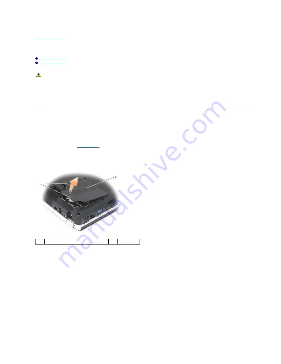
Loosen the two captive screws on the Mini Card compartment cover, then remove the cover and set it aside.  


4.

Disconnect the antenna cables from the WLAN card.  


CAUTION: 

Before you begin any of the procedures in this section, follow the safety instructions in the 

Product Information Guide

.

captive screws (2) 

cover 

Summary of Contents for 1700 - Personal Laser Printer B/W

Page 1: ...Inc disclaims any proprietary interest in trademarks and trade names other than its own Model PP22X June 2007 Rev A00 Before You Begin ExpressCards Using the Memory Card Reader Optical Drive Hard Drive Hinge Cover Internal Card With Bluetooth Wireless Technology Keyboard Memory Display Palm Rest Wireless Mini Cards Flash Cache Module FCM Modem Coin Cell Battery Graphics Card Assembly Processor The...

Page 2: ...Removing the Hinge Cover 5 Remove the keyboard see Removing the Keyboard 6 Remove the display assembly see Removing the Display Assembly 7 Remove the internal card with Bluetooth wireless technology if installed see Removing the Bluetooth Card 8 Remove the palm rest see Removing the Palm Rest 9 Remove the M2 5 x 5 mm screw that secures the wireless sniffer board to the base of the computer 10 Lift...

Page 3: ...g the Audio Connector Board 1 Follow the instructions in Before You Begin 2 Remove the optical drive see Removing the Optical Drive 3 Remove the hard drive see Removing a Hard Drive 4 Remove the hinge cover see Removing the Hinge Cover 5 Remove the keyboard see Removing the Keyboard 6 Remove the display assembly see Removing the Display Assembly 7 Remove the internal card with Bluetooth wireless t...

Page 4: ...cing the Hinge Cover 9 Replace the hard drive see Replacing a Hard Drive 10 Replace the optical drive see Replacing the Optical Drive Consumer Infrared CIR Board Removing the CIR Board 1 Follow the instructions in Before You Begin 2 Remove the optical drive see Removing the Optical Drive 3 Remove the hard drive see Removing a Hard Drive 4 Remove the hinge cover see Removing the Hinge Cover 5 Remov...

Page 5: ... wireless technology if installed see Replacing the Bluetooth Card 6 Replace the display assembly see Replacing the Display Assembly 7 Replace the keyboard see Replacing the Keyboard 8 Replace the hinge cover see Replacing the Hinge Cover 9 Replace the hard drive see Replacing a Hard Drive 10 Replace the optical drive see Replacing the Optical Drive USB Connector Board Removing the USB Connector B...

Page 6: ...ith the screw holes in the base of the computer and then lower the board into place 2 Replace the two M2 5 x 5 mm screws and secure the USB connector board to the base of the computer 3 Connect the USB cable to the USB connector board 4 Replace the palm rest see Replacing the Palm Rest 5 Replace the internal card with Bluetooth wireless technology if installed see Replacing the Bluetooth Card 6 Re...

Page 7: ...e computer 3 Replace the system board see Replacing the System Board Assembly 4 Replace the modem Replacing the Modem ExpressCard Cage Removing the ExpressCard Cage CAUTION Before you begin the following procedure follow the safety instructions in the Product Information Guide NOTICE Before you remove the modem connector observe how the cable is routed on the base of the computer to ensure proper ...

Page 8: ...placing the ExpressCard Cage 1 Align the screw holes on the ExpressCard cage with the screw holes on the base of the computer then lower the ExpressCard cage into place 2 Replace the four M2 5 x 5 mm screws and secure the ExpressCard cage to the base of the computer 3 Replace the palm rest see Replacing the Palm Rest 4 Replace the internal card with Bluetooth wireless technology if installed see R...

Page 9: ...acing the CIR Board 4 Replace the audio connector board see Replacing the Audio Connector Board 5 Replace the wireless sniffer board see Replacing the Wireless Sniffer Board 6 Complete the replacement of the computer base by following the procedures in Replacing the System Board Assembly Back to Contents Page CAUTION Before you begin the following procedure follow the safety instructions in the Pr...

Page 10: ...ar differently than shown in this document CAUTION Before you begin any of the procedures in this section follow the safety instructions in the Product Information Guide NOTICE Only a certified service technician should perform repairs on your computer Damage due to servicing that is not authorized by Dell is not covered by your warranty NOTICE To avoid electrostatic discharge ground yourself by u...

Page 11: ...es until they click into place 8 Slide the battery out of the battery bay 9 Turn the computer top side up open the display and press the power button to ground the system board Back to Contents Page 1 battery 2 battery release latch 2 ...

Page 12: ...ery is properly installed and a network cable is attached 2 Turn on the computer 3 Locate the latest BIOS update file for your computer at support dell com 4 Click Download Now to download the file 5 If the Export Compliance Disclaimer window appears click Yes I Accept this Agreement The File Download window appears 6 Click Save this program to disk and then click OK The Save In window appears 7 C...

Page 13: ...9 Double click the file icon on the desktop and follow the instructions on the screen Back to Contents Page ...

Page 14: ... 4 Grasp the connector end of the card and slide it out from under the securing tabs Replacing the Bluetooth Card 1 Follow the procedures in Before You Begin 2 Replace the card at an angle to slide it under the securing tabs in the card compartment 3 Connect the cable to the card 4 Replace the hinge cover see Replacing the Hinge Cover Back to Contents Page CAUTION Before you begin any of the proce...

Page 15: ...r is running The computer automatically detects the card Memory cards are generally marked with a symbol such as a triangle or an arrow or a label to indicate which end to insert into the slot The cards are keyed to prevent incorrect insertion If card orientation is not clear see the documentation that came with the card 1 Hold the card with the top side of the card facing up 2 Slide the card into...

Page 16: ... the memory card and automatically loads the appropriate device driver If the configuration program tells you to load the manufacturer s drivers use the media that came with the memory card if applicable Back to Contents Page ...

Page 17: ... 3 Loosen the captive screw on the memory module cover then remove the cover and set it aside 4 Disconnect the coin cell battery cable from the system board 5 Slide the battery out of the mylar sleeve Replacing the Coin Cell Battery CAUTION Before you begin any of the procedures in this section follow the safety instructions in the Product Information Guide 1 memory module cover 2 captive screw 1 ...

Page 18: ...to the system board 3 Slide the coin cell battery into the mylar sleeve 4 Replace the memory module cover and tighten the captive screw Back to Contents Page CAUTION Before you begin any of the procedures in this section follow the safety instructions in the Product Information Guide ...

Page 19: ...rmal cooling assembly see Removing the Processor Thermal Cooling Assembly 10 To loosen the ZIF socket use a small flat blade screwdriver and rotate the ZIF socket cam screw counterclockwise until it comes to the cam stop 11 Lift the processor module from the ZIF socket CAUTION Before you begin the following procedure follow the safety instructions in the Product Information Guide NOTICE To avoid d...

Page 20: ...Back to Contents Page CAUTION Before you begin the following procedure follow the safety instructions in the Product Information Guide NOTICE Do not touch the processor die Press and hold the processor down on the substrate on which the die is mounted while turning the cam screw to prevent intermittent contact between the cam screw and processor NOTICE Ensure that the cam lock is in the fully open...

Page 21: ......

Page 22: ...t 9 In sequential order loosen the four captive screws that secure the processor thermal cooling assembly to the system board then carefully lift the processor thermal cooling assembly out of the computer Replacing the Processor Thermal Cooling Assembly 1 Align the four captive screws on the processor thermal cooling assembly with the screw holes on the system board 2 In sequential order tighten t...

Page 23: ...play Assembly 6 Replace the keyboard see Replacing the Keyboard 7 Replace the hinge cover see Replacing the Hinge Cover 8 Replace the hard drive see Replacing a Hard Drive 9 Replace the optical drive see Replacing the Optical Drive Back to Contents Page ...

Page 24: ...re the Mini Card compartment cover then remove the cover and set it aside 4 Disconnect antenna cables from any installed Mini Cards see Wireless Mini Cards 5 Remove the two M2 5 x 8 mm screws from the bottom of the computer 6 Remove the two M2 5 x 8 mm screws from the back of the computer 7 Remove the hinge cover see Removing the Hinge Cover 8 Remove the keyboard see Removing the Keyboard CAUTION ...

Page 25: ...e plastic tabs on the palm rest 5 Connect the camera microphone cable to the camera microphone cable connector on the system board 6 Connect the display cable to the display cable connector on the system board 7 Replace and tighten the captive grounding screw 8 Replace the keyboard see Replacing the Keyboard 9 Replace the hinge cover see Replacing the Hinge Cover 10 Replace the two M2 5 x 8 mm scr...

Page 26: ...the Display Assembly 5 Remove the four rubber display bumpers and two mylar screw covers from around the display bezel 6 Remove the six M2 5 x 4 2 mm shoulder screws from around the display bezel 7 Starting at the top corner of the display panel use your fingers to separate the bezel from the top cover then lift the inside edges to separate the remainder of the bezel CAUTION Before you begin the f...

Page 27: ...ard see Replacing the Keyboard 4 Remove the display assembly see Removing the Display Assembly 5 Remove the display bezel see Removing the Display Bezel 6 Remove the eight M2 x 3 mm screws four on each side of the display panel from around the display panel 7 Remove the two M2 5 x 5 mm screws from the bottom of the display panel 8 Lift the top of the display panel then rotate the camera microphone...

Page 28: ... connector latch downward to secure the cable 6 Gently lower the display panel into place 7 Replace the two M2 5 x 5 mm screws at the bottom of the display panel 8 Replace the eight M2 x 3 mm screws four on each side of the display panel to secure the display panel to the display cover 9 Replace the display bezel see Replacing the Display Bezel 10 Replace the display assembly see Replacing the Dis...

Page 29: ...latch cover from the display cover 10 Remove the display latch spring and set it aside 11 Slide the display latch to the right then carefully flex the left side and lift to detach the left side from the display latch cover Slide the display latch to the left then carefully flex the right side and lift to detach the right side from the cover 1 wireless antenna cover screws two M2 x 3 mm screws 2 ca...

Page 30: ...zel see Replacing the Display Bezel 9 Replace the display assembly see Replacing the Display Assembly 10 Replace the keyboard see Replacing the Keyboard 11 Replace the hinge cover see Replacing the Hinge Cover Camera and Microphone Assembly Removing the Camera and Microphone Assembly 1 Follow the instructions in Before You Begin 2 Remove the hinge cover see Removing the Hinge Cover 3 Remove the ke...

Page 31: ...e camera and microphone assembly to the display cover 4 Replace the display panel see Replacing the Display Panel 5 Replace the display bezel see Replacing the Display Bezel 6 Replace the display assembly see Replacing the Display Assembly 7 Replace the keyboard see Replacing the Keyboard 8 Replace the hinge cover see Replacing the Hinge Cover Back to Contents Page CAUTION Before you begin the fol...

Page 32: ...ith Bluetooth wireless technology if installed see Removing the Bluetooth Card 8 Remove the palm rest see Removing the Palm Rest 9 Remove the graphics card assembly if installed see Removing the Graphics Card Assembly 10 Remove the processor thermal cooling assembly see Removing the Processor Thermal Cooling Assembly 11 Disconnect the fan connector from the system board connector 12 In sequential ...

Page 33: ...the Graphics Card Assembly 6 Replace the palm rest see Replacing the Palm Rest 7 Replace the internal card with Bluetooth wireless technology if installed see Replacing the Bluetooth Card 8 Replace the display assembly see Replacing the Display Assembly 9 Replace the keyboard see Replacing the Keyboard 10 Replace the hinge cover see Replacing the Hinge Cover 11 Replace the hard drive see Replacing...

Page 34: ...etal connectors on the back of the computer 4 Release the FCM by pushing the metal securing brackets away from the card until the card pops up slightly 5 Remove the FCM Replacing the FCM 1 Insert the FCM connector at a 45 degree angle into the system board connector labeled FCM 2 Press the other end of the FCM down into the securing tabs until the card clicks into place Back to Contents Page NOTE ...

Page 35: ...ve screws that secure the graphics card assembly to the system board then carefully lift the assembly out of the computer Replacing the Graphics Card Assembly 1 Align the three captive screws on the graphics card assembly assembly with the screw holes on the system board 2 In sequential order tighten the three captive screws to secure the graphics card assembly assembly to the system board 3 Repla...

Page 36: ...play Assembly 6 Replace the keyboard see Replacing the Keyboard 7 Replace the hinge cover see Replacing the Hinge Cover 8 Replace the hard drive see Replacing a Hard Drive 9 Replace the optical drive see Replacing the Optical Drive Back to Contents Page ...

Page 37: ...hard drive out of the hard drive bay NOTE Dell does not guarantee compatibility or provide support for hard drives obtained from sources other than Dell CAUTION Before you begin any of the procedures in this section follow the safety instructions in the Product Information Guide CAUTION Do not touch the metal housing of the hard drive if you remove the hard drive from the computer while the drive ...

Page 38: ...all the drivers and utilities for your computer as needed see Reinstalling Drivers and Utilities in your Owner s Manual Back to Contents Page 1 secondary hard drive bay 2 M2 5 x 5 mm screws 3 3 primary hard drive 4 pull tab CAUTION Before you begin any of the procedures in this section follow the safety instructions in the Product Information Guide NOTICE Hard drives are extremely fragile Exercise...

Page 39: ... cover with the corresponding notches in the computer 3 Moving from left to right press down until the hinge cover snaps into place Back to Contents Page CAUTION Before you begin any of the procedures in this section follow the safety instructions in the Product Information Guide NOTICE The hinge cover is fragile and can be damaged if extreme force is used Exercise care when removing the hinge cov...

Page 40: ...edge of the palm rest 3 Align the notch at the top of the keyboard with the tab on the palm rest and then lower the keyboard into place 4 Applying even pressure to keep the keyboard flat slide the keyboard towards the front of the computer to connect the keyboard connector and secure the six tabs along the front edge of the keyboard beneath the front inside edge of the palm rest Ensure that the ta...

Page 41: ...the four M2 x 3 mm screws at the top of the keyboard 6 Replace the hinge cover see Replacing the Hinge Cover Back to Contents Page 1 tabs 6 2 keyboard connector 3 notch on keyboard 4 tab on palm rest 5 palm rest ...

Page 42: ...tery latch assembly then press the button into place 4 Replace the computer base see Replacing the Computer Base CAUTION Before you begin the following procedure follow the safety instructions in the Product Information Guide NOTICE The battery latch spring is not secured to the latch assembly and can be easily misplaced When removing the battery latch assembly place the spring in a secure locatio...

Page 43: ...Back to Contents Page ...

Page 44: ... see Removing the Keyboard 4 Use your fingertips to carefully spread apart the securing clips on each end of the memory module connector until the module pops up 5 Remove the module from the connector DIMM B Memory Module The DIMM B memory module is located under the memory module cover on the bottom of the computer NOTICE If your computer has only one memory module install the memory module in th...

Page 45: ...gn the notch in the memory module edge connector with the tab in the connector slot 3 Slide the memory module firmly into the slot at a 45 degree angle and rotate the module down until it clicks into place If you do not feel the click remove the module and reinstall it 1 memory module cover 2 captive screw NOTICE To prevent damage to the memory module connector do not use tools to spread the memor...

Page 46: ... The DIMM B memory module is located under the memory module cover on the bottom of the computer 1 Follow the procedures in Before You Begin 2 Turn the computer over 3 Loosen the captive screw on the memory module cover then remove the cover and set it aside 4 Align the notch in the module edge connector with the tab in the connector slot 5 Slide the module firmly into the slot at a 45 degree angl...

Page 47: ...s the computer boots it detects the additional memory and automatically updates the system configuration information To confirm the amount of memory installed in the computer click Start Help and Support Dell System Information Back to Contents Page 1 tab 2 notch NOTICE If the cover is difficult to close remove the module and reinstall it Forcing the cover to close may damage your computer ...

Page 48: ...ork WLAN l Mobile Broadband or Wireless Wide Area Network WWAN l Wireless Personal Area Network WPAN Removing a Mini Card WLAN Card 1 Follow the procedures in Before You Begin 2 Turn the computer over 3 Loosen the two captive screws on the Mini Card compartment cover then remove the cover and set it aside 4 Disconnect the antenna cables from the WLAN card CAUTION Before you begin any of the proced...

Page 49: ...m board connector Mobile Broadband or WWAN Card 1 Follow the procedures in Before You Begin 2 Turn the computer over 3 Loosen the two captive screws on the Mini Card compartment cover then remove the cover and set it aside 1 antenna cable connectors 2 2 WLAN card 1 metal securing tabs 2 2 WLAN card NOTE WWAN is also available on an ExpressCard see ExpressCards ...

Page 50: ... card 5 Release the WWAN card by pushing the metal securing tabs toward the back of the computer until the card pops up slightly 6 Lift the WWAN card out of its system board connector 1 captive screws 2 2 cover 1 antenna cable connectors 2 2 WWAN card ...

Page 51: ...the cover and set it aside 4 Disconnect the blue antenna cable from the WPAN card 5 Release the WPAN card by pushing the metal securing tabs toward the back of the computer until the card pops up slightly 6 Lift the WPAN card out of its system board connector 1 metal securing tabs 2 2 WWAN card 1 captive screws 2 2 cover 1 WPAN card 2 antenna cable connector ...

Page 52: ...e captive screws Mobile Broadband or WWAN Card 1 Insert the WWAN card connector at a 45 degree angle into the system board connector labeled WWAN 2 Press the other end of the WWAN card down into the securing tabs until the card clicks into place 3 Connect the black antenna cable with a gray stripe to the connector labeled aux black triangle and connect the white antenna cable with a gray stripe to...

Page 53: ...nnect the blue antenna cable to the WPAN card 4 Secure unused antenna cables in the protective mylar sleeve 5 Replace the cover and tighten the captive screws Back to Contents Page NOTICE The connectors are keyed to ensure correct insertion If you feel resistance check the connectors on the card and on the system board and realign the card NOTICE To avoid damage to the WPAN card never place cables...

Page 54: ...ess technology if installed see Removing the Bluetooth Card 8 Remove the palm rest see Removing the Palm Rest 9 Remove the two M2 x 3 mm screws that attach the modem to the system board and the base of the computer 10 Pull up on the pull tab to disconnect the modem from the modem connector on the system board 11 Disconnect the modem cable from the modem Replacing the Modem CAUTION Before you begin...

Page 55: ...alm Rest 6 Replace the internal card with Bluetooth wireless technology if installed see Replacing the Bluetooth Card 7 Replace the display assembly see Replacing the Display Assembly 8 Replace the keyboard see Replacing the Keyboard 9 Replace the hinge cover see Replacing the Hinge Cover 10 Replace the hard drive see Replacing a Hard Drive 11 Replace the optical drive see Replacing the Optical Dr...

Page 56: ...the bay 5 Slide the optical drive out of the bay Replacing the Optical Drive 1 Follow the procedures in Before You Begin 2 Slide the optical drive into the bay 3 Turn the computer over 4 Replace and tighten the device security screw as needed Back to Contents Page CAUTION Before you begin any of the procedures in this section follow the safety instructions in the Product Information Guide 1 optica...

Page 57: ...Removing the Display Assembly 7 Remove the internal card with Bluetooth wireless technology if installed see Removing the Bluetooth Card 8 Remove the sixteen M2 5 x 8 mm screws from the bottom of the computer 9 Turn the computer over and remove the six M2 0 x 3 mm screws that secure the top of the palm rest 10 Disconnect the touch pad connector from the system board CAUTION Before you begin the fo...

Page 58: ...see Replacing the Display Assembly 7 Replace the keyboard see Replacing the Keyboard 8 Replace the hinge cover see Replacing the Hinge Cover 9 Replace the hard drive see Replacing a Hard Drive 10 Replace the optical drive see Replacing the Optical Drive Back to Contents Page 1 palm rest 2 computer base 3 touch pad connector NOTICE Do not use force to separate the palm rest from the computer If you...

Page 59: ...on on supported ExpressCards ExpressCard Blanks Your computer shipped with a plastic blank installed in the ExpressCard slot Blanks protect unused slots from dust and other particles Save the blank for use when no ExpressCard is installed in the slot Removing an ExpressCard or Blank Press the release button and remove the card or blank For some release buttons you must press the button twice once ...

Page 60: ...e slot and the top side of the card facing up The latch may need to be in the in position before you insert the card 2 Slide the card into the slot until the card is completely seated in its connector If you encounter too much resistance do not force the card Check the card orientation and try again The computer recognizes the ExpressCard and automatically loads the appropriate device driver If th...

Page 61: ... USB Connector Video Connector S Video TV Out Connector 1394 Connector USB Connector Video Connector S Video TV Out Connector Pin Signal 1 USB5V 2 USBP 3 USBP 4 GND Pin Signal Pin Signal 1 CRT_R 9 5V 2 CRT_G 10 GND 3 CRT_B 11 MONITOR_DETECT 4 NC 12 DDC_DATA 5 GND 13 CRT_HS 6 GND 14 CRT_VS 7 GND 15 DDC_CLK 8 GND ...

Page 62: ...1394 Connector Back to Contents Page S Video Pin Signal 1 GND 2 GND 3 DLUMA L 4 DCRMA L Pin Signal 1 TPB 2 TPB 3 TPA 4 TPA ...

Page 63: ...e Bluetooth Card 8 Remove the palm rest see Removing the Palm Rest 9 Disconnect the speaker cable from the system board 10 Remove the two M2 5 x 5 mm screws that secure the speaker assembly to the base of the computer 11 Remove the speaker assembly Replacing the Speaker Assembly 1 Align the guide holdes in the speaker assembly with the guide posts on the base of the computer then lower the assembl...

Page 64: ...ology if installed see Replacing the Bluetooth Card 6 Replace the display assembly see Replacing the Display Assembly 7 Replace the keyboard see Replacing the Keyboard 8 Replace the hinge cover see Replacing the Hinge Cover 9 Replace the hard drive see Replacing a Hard Drive 10 Replace the optical drive see Replacing the Optical Drive Back to Contents Page ...

Page 65: ...bly 9 Remove the internal card with Bluetooth wireless technology if installed see Removing the Bluetooth Card 10 Remove the palm rest see Removing the Palm Rest 11 Remove the DIMM A memory module see Removing a Memory Module 12 Remove the modem see Removing the Modem 13 Remove the graphics card assembly if installed see Removing the Graphics Card Assembly 14 Remove the processor thermal cooling a...

Page 66: ... to the system board 5 Connect the speaker cable to the system board 6 Connect one end of the cable for the Bluetooth card with wireless technology to the system board 7 Connect the USB I O cable to the system board 8 Replace the fan see Replacing the Fan 9 Replace the processor see Replacing the Processor Module 10 Replace the processor thermal cooling assembly see Replacing the Processor Thermal...

Page 67: ...mory Module 20 Replace all Mini Cards see Replacing a Mini Card 21 Replace the hard drive see Replacing a Hard Drive 22 Replace the optical drive see Replacing the Optical Drive 23 Turn on the computer 24 Flash update the BIOS see Flashing the BIOS for more information 25 Enter the system setup program to update the BIOS on the new system board with the computer Service Tag Back to Contents Page N...

Page 68: ... trademarks of Microsoft Corporation in the United States and or other countries Other trademarks and trade names may be used in this document to refer to either the entities claiming the marks and names or their products Dell Inc disclaims any proprietary interest in trademarks and trade names other than its own June 2007 Rev A00 Back to Contents Page NOTE A NOTE indicates important information t...

Reviews: