


Component
Image
Power cords
Bezel for disk processor
enclosure (1)
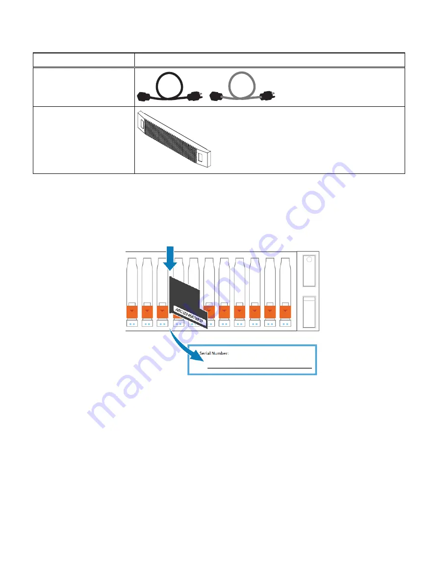
Record the product serial number from the DPE
The PSNT for the 25-slot DPE is a black pull-out tag that is located between the
drives in slots 16 and 17.
Figure 1 Location of the product serial number tag
Pull the tag out and record the product serial number from the tag on the
Configuration Worksheet. The product serial number is three letters followed by 11
numbers. After recording the information, return the tag to its inserted position.
Install the rails in the cabinet
This task describes the procedure to install one rail. After installing one rail, repeat the
procedure for the other rail. The procedure is the same for both the left and right rail.
You can install the rails into either a square or round hole rack.
Procedure
1. Position the rail end piece so the label FRONT is located at the front of the rack
and facing towards the inside of the rack, while orienting the rear of the rail to
align level with the holes on the rear of the rack.
2. From the rear of the rack, pull the rail straight back until the latch is locked.
3. To install the front end piece of the rail, press the blue latch release button until
the latch rotates open.
Installation Procedures
Record the product serial number from the DPE
13


