You should hear a click as the latch handle engages and secures the IOM to its connector on the back of the midplane.
5
Reconnect the cables.
NOTE:
In a dual-controller system in which PFU is enabled, when you update the firmware on one controller, the system
automatically updates the partner controller.
Removing an expansion module
Before you begin any procedure, see
NOTE:
Considerations for removing controller modules:
•
Expansion enclosures are equipped with dual-IOMs. You may hot-swap a single expansion module in an operational enclosure.
•
If replacing both expansion modules,—and the expansion module is online—you can hot-swap the module in IOM slot “A”, and then
hot-swap the module in IOM slot “B”, verifying each module is recognized by the controller.
•
Do not remove a faulty module unless its replacement is on-hand. All modules must be in place when the system is in operation.
Illustrations in the controller module replacement procedures show rear panel views of the enclosure, and IOMs are properly aligned for
insertion into the IOM slots.
1
Locate the expansion enclosure containing the expansion module that must be replaced. On the enclosure front panel, check for an
amber fault condition on the enclosure’s Ops panel (left ear). On the enclosure rear panel, look for amber illumination of the expansion
module’s Fault LED.
2
Disconnect any cables connected to the expansion module.
Label each cable to facilitate re-connection to the replacement IOM.
3
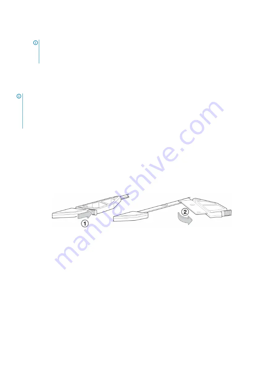
Grasp the module latch between the thumb and forefinger, and squeeze the flange and handle together to release the latch handle
from its docking member (detail No.1), and swing the latch out to release the IOM from its seated position (detail No.2) as shown in
Figure 55. IOM latch operation detail
Figure 57. IOM latch operation detail
4
Swing the latch handle open as shown in detail No.2 within
70
Module removal and replacement


