background image

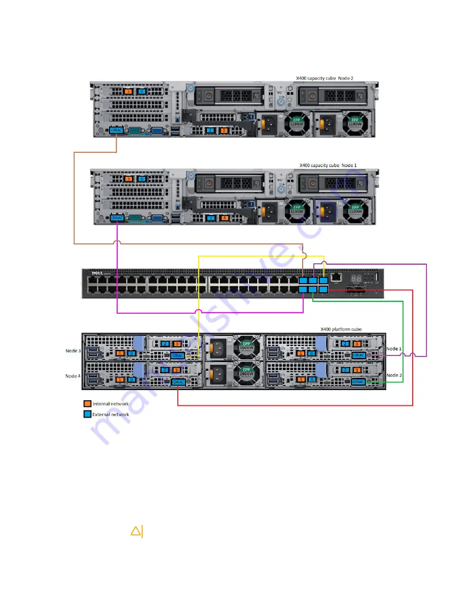
Figure 34 iDRAC cabling

Connect network cables

To deploy the X400 hardware, there are requirements and considerations for onsite
networking, switches, and cabling.

An X400 Appliance requires both an isolated internal (private) Ethernet network and
an external (public) Ethernet network. The internal network uses a non-routable
private VLAN and is for the internal X400 Appliance communication.

CAUTION

 The internal network must be isolated from any other traffic.

The external network connection uses a routable public VLAN to communicate with
the rest of the company network where the backup targets will be located. The
external network is used for data backup. You should consult with your network

Cabling and network requirements

PowerProtect X400 Appliance Hardware Configuration and Installation Guide

49

Summary of Contents for PowerProtect X400

Page 1: ...PowerProtect X400 Appliance Version 1 1 Hardware Configuration and Installation Guide 302 005 719 Rev 03 August 2019 ...

Page 2: ...ALLY DISCLAIMS IMPLIED WARRANTIES OF MERCHANTABILITY OR FITNESS FOR A PARTICULAR PURPOSE USE COPYING AND DISTRIBUTION OF ANY DELL SOFTWARE DESCRIBED IN THIS PUBLICATION REQUIRES AN APPLICABLE SOFTWARE LICENSE Dell Technologies Dell EMC Dell EMC and other trademarks are trademarks of Dell Inc or its subsidiaries Other trademarks may be the property of their respective owners Published in the USA De...

Page 3: ... the rails 30 Secure the rail assemblies to the rack 32 Install the X400 capacity cube in the rack 32 Install the front bezel 34 Install the X400 platform cube 35 Identifying the rail kit components 35 Install the rails 36 Install the X400 platform cube in the rack 37 Install the optional chassis retention bracket 38 Configure switches 39 Configure two switches in the X400 Appliance 40 Configure a...

Page 4: ...es SRS gateway myservice360 account 62 Obtain the Dell EMC PowerProtect X400 license file 62 Install mDNS on the laptop used for the initial login to the PowerProtect X400 Appliance Configuration UI 63 Power on the X400 cubes 64 Configure the X400 Apliance in the UI 67 Introduction 68 Connect to the X400 Appliance 68 Configure the X400 Appliance 72 Set up the X400 Appliance support settings 74 Log...

Page 5: ... inner rails out of the rack 33 Install the X400 capacity cube in the rails 33 Slide the X400 capacity cube into the rack 34 Installing the front bezel 35 Static rail assembly 36 Installing the static rail 37 Install the X400 platform cube in the rails 38 Install the chassis retention bracket to the rack 38 Dual switch configuration in the X400 Appliance 40 X400 platform cube and X400 capacity cub...

Page 6: ...Figures 6 PowerProtect X400 Appliance Hardware Configuration and Installation Guide ...

Page 7: ...e and X400 capacity cube node network port cabling connections for dual switch configuration 41 X400 platform cube and X400 capacity cube node network port cabling connections for single switch configuration 44 Internal network requirements 59 External network requirements 61 1 2 3 4 5 6 7 8 TABLES PowerProtect X400 Appliance Hardware Configuration and Installation Guide 7 ...

Page 8: ...Tables 8 PowerProtect X400 Appliance Hardware Configuration and Installation Guide ...

Page 9: ...ontains the following topics l PowerProtect X400 introduction 10 l X400 capacity cube storage capacity 11 l Hardware and software required for installation 11 PowerProtect X400 Appliance Hardware Configuration and Installation Guide 9 ...

Page 10: ... on an X400 capacity cube must run at the same speed Note Network switches are not included in the X400 hardware and must be purchased separately or provided by the user A cube is defined as the basic building block of the X400 Appliance Each cube is comprised of one or more nodes which contribute memory compute networking and storage to the overall cube A PowerProtect X400 Appliance includes one ...

Page 11: ... 96 160 192 256 288 352 384 X400F capacity cube 64 112 176 224 288 336 400 448 Hardware and software required for installation Before installing the X400 platform cube and the X400 capacity cubes review the following table to understand the hardware and software requirements for X400 cube installation Table 2 Hardware and software requirements for cube installation Component Description Sliding ra...

Page 12: ...within all X400 capacity cubes must match SFPs for switches Customer supplied if optical SFP cables are used LC to LC optical cables The LC to LC optical cables are an option and can be ordered from Dell EMC or can be customer supplied RJ45 network cables Cat6 cables for connecting to iDRAC network connection Optional but strongly recommended iDRAC configuration and cabling provides an out of band...

Page 13: ...e specifications This chapter contains the following topics l X400 platform cube 14 l X400 capacity cube 20 l Third party rack requirements 28 PowerProtect X400 Appliance Hardware Configuration and Installation Guide 13 ...

Page 14: ... 5118 12 core processor 8 x 16 GB RDIMMs 128 GB Power 2 x 1600W Platinum Heat dissipation maximum 475 BTU hr Frequency 50 60 Hz Voltage 100 240 V AC auto ranging Maximum input current 10 A HDDs in front slots 4 x 12 TB SAS HDDs total SSDs in front slots 4 x 1 92 TB SSDs total For information on the environmental specifications of the X400 platform cube see the Dell EMC PowerEdge C6400 environmenta...

Page 15: ... appliance serial number is required for configuring the X400 Appliance in the PowerProtect X400 Appliance Configuration UI See Figure 8 on page 20 Figure 2 Sled to drive mapping 1 Drives 0 2 mapped to sled 1 2 Drives 3 5 mapped to sled 2 3 Drives 6 8 mapped to sled 3 4 Drives 9 11 mapped to sled 4 Sled location on the back of the X400 platform cube is shown in Figure 6 on page 18 Hardware specifi...

Page 16: ...ower button to turn the sled on or off The power on indicator turns amber when a critical system event occurs 4 System identification button for sleds 1 and 3 Press the system ID button l To locate a particular sled within the enclosure l To turn the system ID on or off 5 Power on indicator or system state indicator or power button for sleds 2 and 4 Press the power button to turn the sled on or of...

Page 17: ... Fan cage 2 4 Fan 4 5 Right linking board 6 Backplane 7 Drive cage 8 Expander board 9 Left midplane 10 Left linking board 11 Chassis management board 12 Power interposer board Hardware specifications PowerProtect X400 Appliance Hardware Configuration and Installation Guide 17 ...

Page 18: ...iller to protect the connector 7 Supporting bracket 8 M 2 SATA riser 9 Memory slot 4 10 PCIe expansion card riser assembly X400 platform cube rear view The X400 platform cube chassis provides dual hot swappable power supplies with 1 1 redundancy auto sensing and auto switching capability Figure 6 X400 platform cube chassis rear view Hardware specifications 18 PowerProtect X400 Appliance Hardware C...

Page 19: ...e device to the sled 9 10 GbE port 2 N A Left port connects to internal network right port connects to external network 10 Information tag luggage tag pull out tab N A This tab has the sled serial number sled part number Express Service Code Service Tag and MAC address labels 11 System identification indicator The System Identification ID LED is available on the back of the system Press the system...

Page 20: ... cm 29 75 inch Maximum configuration weight 36 5 kg 80 47 lb Empty weight 18 9 kg 41 67 lb Per node configuration X400H capacity cube Front panel 12 x 12 TB SAS HDD Back panel 1 x 12 TB SAS HDD and 1 x 1 92 TB SSD Middle panel 1 x 3 84 TB SSD 3 x 12 TB SAS HDD Total 18 drives 16 x 12 TB HDDs 1 x 1 92 TB SSD 1 x 3 84 TB SSD 4 x 10 25 GbE ports 1 x 1 Gb BASE T for iDRAC 2 x Intel Xeon 5118 2 x 12 co...

Page 21: ... information on the environmental specifications of the X400 capacity cube see the Dell EMC PowerEdge R740xd environmental specifications X400 capacity cube front and internal views The following figure shows the X400 capacity cube 2U chassis front with 12 x 3 5 drive slots The hybrid X400 capacity cube model contains twelve hot swappable 12 TB SAS HDDs in slots 0 11 in the front panel The flash X...

Page 22: ...tem health and system ID indicator code Condition Solid blue Indicates that the system is turned on system is healthy and system ID mode is not active Press the system health and system ID button to switch to system ID mode Blinking blue Indicates that the system ID mode is active Press the system health and system ID button to switch to system health mode Solid amber Indicates that the system is ...

Page 23: ...tatus LEDs decoded view HDD Thermal PSU DIMM PCI Figure 12 Right control panel 1 Power button with integrated power LED 2 Two USB 3 0 ports 3 Micro USB for iDRAC Direct This is not supported on the X400 capacity cube 4 Status LED for iDRAC Direct 5 VGA port Hardware specifications PowerProtect X400 Appliance Hardware Configuration and Installation Guide 23 ...

Page 24: ...e expander card 3 Cooling fan 6 in the cooling fan assembly 4 Air shroud 5 Expansion card riser 2 6 Network daughter card 7 System board 8 Expansion card riser 1 9 Integrated storage controller card Hardware specifications 24 PowerProtect X400 Appliance Hardware Configuration and Installation Guide ...

Page 25: ...y 5 Mid drive backplane 6 Rear drive backplane 7 Drive 2 in the rear drive cage 8 System board 9 Expansion card riser 1 10 Integrated storage controller card X400 capacity cube rear view The X400 capacity cube chassis provides dual hot swappable power supplies with 1 1 redundancy auto sensing and auto switching capability Hardware specifications PowerProtect X400 Appliance Hardware Configuration a...

Page 26: ...nd 1 x 1 92 TB SSD in drive slot 13 on the right 6 Power supply unit 2 N A 2 x 1100W AC power supply units PSUs 7 10 25 GbE port 2 N A Left port connects to the external network right port connects to the internal network These two ports are located in the Network Daughter Card 8 USB port 2 Do not use the two USB ports on the X400 capacity cube 9 VGA port Enables you to connect a display device to...

Page 27: ...tag pull out tab The information tag pull out tab is located in the front of the X400 capacity cube under slot 11 Figure 16 Close up view of the serial number on the X400 capacity cube information tag Figure 17 X400 capacity cube information tag Hardware specifications PowerProtect X400 Appliance Hardware Configuration and Installation Guide 27 ...

Page 28: ...inches of clearance in the rear of the rack to allow for service area and proper airflow Power The customer provided rack should have redundant power zones one on each side of the rack with separate PDU power strips Each redundant power zone should have capacity for the maximum power load When configured this way the X400 Appliance will remain up and running even with the failure of one power zone...

Page 29: ...ll X400 cubes in the rack This chapter contains the following topics l Install the X400 capacity cube 30 l Install the X400 platform cube 35 PowerProtect X400 Appliance Hardware Configuration and Installation Guide 29 ...

Page 30: ...00 capacity cube cover can be removed to access the internal FRUs Figure 18 Sliding rail assembly 1 Sliding rail 2 2 Velcro strap 2 3 Screw 4 4 Washer 4 Install the rails About this task The rails are labeled left and right and cannot be interchanged The front side of each rail is labeled Left Front or Right Front when the rail faces the rack front Procedure 1 Determine where to mount the X400 cap...

Page 31: ...ear of the rack until the latch locks in place Figure 19 Installing the rear end of the rail 5 For the front end piece rotate the latch outward and pull the rail forward until the pins slide into the flange and release the latch to secure the rail in place Figure 20 Installing the front end of the rail 6 Repeat the preceding steps to install the right rail assembly Install X400 cubes in the rack P...

Page 32: ...nated U spaces 2 Insert and tighten the two screws using the Phillips 2 screwdriver Figure 21 Installing screws Install the X400 capacity cube in the rack This procedure is used to install the X400 capacity cube in the rack About this task WARNING The X400 capacity cube is heavy and should be installed in the rack by two people To avoid personal injury and or damage to the equipment do not attempt...

Page 33: ...wnward until all the rail standoffs are seated in the J slots Figure 23 Install the X400 capacity cube in the rails 4 Push the X400 capacity cube inward until the lock levers click into place 5 Pull the blue slide release lock tabs forward on both rails and slide the X400 capacity cube into the rack The slam latches will engage to secure the X400 capacity cube in the rack Install X400 cubes in the...

Page 34: ...dure to install the front bezel with the LCD panel and the front bezel without the LCD panel is the same Procedure 1 Align and insert the right end of the bezel onto the X400 capacity cube 2 Press the release button and fit the left end of the bezel onto the X400 capacity cube 3 Lock the bezel by using the key Install X400 cubes in the rack 34 PowerProtect X400 Appliance Hardware Configuration and...

Page 35: ...platform cube secure the rails to the customer provided rack and install the X400 platform cube into the rack Identifying the rail kit components The 2U static rail assemblies allow the X400 platform cube to be secured in the rack Install X400 cubes in the rack PowerProtect X400 Appliance Hardware Configuration and Installation Guide 35 ...

Page 36: ...t firmly Note The rails can be installed in both square and round hole racks Note The support bracket must be removed if the rail cannot fit between the rack flanges Procedure 1 Press the release latch on the rail 2 Align the rail with the rack flange ensuring that the rail pegs are seated in the designated rack holes 3 Release the latch to lock the rail in place Install X400 cubes in the rack 36 ...

Page 37: ...the rack without a mechanical lift and or help from another person Procedure 1 If installing the optional chassis retention bracket insert two cage nuts in the two rack holes above each rail Note The cage nuts must be installed before installing the X400 platform cube in the rack 2 Position the X400 platform cube on the rail 3 Hold the X400 platform cube rack ears and slide the X400 platform cube ...

Page 38: ...Procedure 1 Place the bracket on the X400 platform cube 2 Secure the bracket to the rack flange with two screws by using Phillips 2 screwdriver Figure 29 Install the chassis retention bracket to the rack 1 Cage nut 4 2 Screw 4 3 Chassis retention bracket 2 Install X400 cubes in the rack 38 PowerProtect X400 Appliance Hardware Configuration and Installation Guide ...

Page 39: ...hes This chapter contains the following topics l Configure two switches in the X400 Appliance 40 l Configure a single switch in the X400 Appliance 43 PowerProtect X400 Appliance Hardware Configuration and Installation Guide 39 ...

Page 40: ...each NIC should go to separate switches and the internal private ports from each NIC should go to separate switches Figure 30 Dual switch configuration in the X400 Appliance Internal VLAN ports within appliance X400 capacity cube Node 2 X400 capacity cube Node 1 X400 platform cube Node 2 Node 1 Node 3 Node 4 1 0 1 0 1 0 1 0 1 0 1 0 2 3 Internal network port External network port Follow the pattern...

Page 41: ...52 54 49 51 53 cap N1 p1 cap N2 p1 cap N3 p1 cap N1 p0 cap N2 p0 cap N3 p0 cap N4 p0 cap N4 p1 plat N4 p3 plat N3 p3 plat N2 p3 plat N1 p3 plat N3 p2 core N1 L core N4 L core N3 L core N2 L core N1 L plat N4 p2 plat N2 p2 core N1 L core N4 L core N3 L core N2 L core N1 L Switch 1 plat N1 p2 1 48 46 44 42 40 38 36 34 32 30 28 26 24 22 20 18 16 14 12 10 8 4 6 2 3 5 7 9 11 13 15 17 19 21 23 25 27 29 ...

Page 42: ...e 4 Port 3 7 Port 2 23 Port 1 7 Port 0 23 Dual switch configuration with existing switch all ports are not free In the scenario where the customer has two existing switches and is going to use the available LAN ports on the switches follow these cabling guidelines l All 0 ports both on the X400 platform cube and theX400 capacity cubes should be connected to the external VLAN on switch 1 l All 2 po...

Page 43: ...it is a 10 GbE or greater SFP switch that supports VLAN Follow the same pattern for connecting X400 capacity cube nodes 3 and 4 Figure 32 Single switch configuration in the X400 Appliance Follow the pattern for capacity cube nodes 3 and 4 X400 platform cube Node 1 Node 2 Node 3 Node 4 Internal VLAN ports within appliance Internal network port External network port X400 capacity cube Node 1 X400 ca...

Page 44: ...8 16 14 12 10 8 4 6 2 3 5 7 9 11 13 15 17 19 21 23 25 27 29 35 31 33 37 39 41 43 45 47 50 52 54 49 51 53 cap N1 p3 cap N2 p3 cap N2 p1 cap N3 p1 cap N1 p1 cap N3 p3 cap N4 p1 cap N1 p2 cap N2 p2 cap N3 p2 cap N4 p2 cap N1 p0 cap N2 p0 cap N3 p0 cap N4 p0 cap N4 p3 plat N4 p1 plat N3 p1 plat N2 p1 plat N1 p1 plat N4 p3 plat N3 p3 plat N2 p3 plat N1 p3 plat N3 p0 plat N1 p2 plat N2 p2 core N1 L core...

Page 45: ...capacity cube node 4 Port 3 7 Port 2 23 Port 1 15 Port 0 31 Single switch configuration with existing switch all ports are not free In the scenario where the customer has an existing switch and is going to use the available LAN ports on the switch follow these cabling guidelines l All even ports both on the X400 platform cube and the X400 capacity cubes ports 0 and 2 should be connected to the ext...

Page 46: ...Configure switches 46 PowerProtect X400 Appliance Hardware Configuration and Installation Guide ...

Page 47: ...d network requirements This chapter contains the following topics l Connect power cables 48 l Connect iDRAC cables 48 l Connect network cables 49 PowerProtect X400 Appliance Hardware Configuration and Installation Guide 47 ...

Page 48: ...ions hostnames 1 GbE RJ 45 for each of the four X400 platform cube sleds and one X400 capacity cube The maximum number of iDRAC connections in an appliance is eight one X400 platform cube and four X400 capacity cubes The 1 GbE management switch to which the iDRAC cables connect must have RJ 45 connections The number of cat 5 6 cables required to connect the iDRAC ports on the X400 cubes to the net...

Page 49: ... uses a non routable private VLAN and is for the internal X400 Appliance communication CAUTION The internal network must be isolated from any other traffic The external network connection uses a routable public VLAN to communicate with the rest of the company network where the backup targets will be located The external network is used for data backup You should consult with your network Cabling a...

Page 50: ... and external networks Before you connect the X400 cubes to the switch es consider the following l X400 cubes are compatible with all SFP switches that support 10 Gbe or 25 Gbe and VLAN If the 10 GbE and 25 GbE switches optional are unique to each other ensure to connect 10 Gbe to 10 Gbe or 25 GbE to 25 GbE Note that if the switches are segregated by speed they must share a common VLAN and be able...

Page 51: ...rotect X400 configuration UI In this case the switch handles the traffic segregation If in trunk mode you must enter the VLANs for each network in the PowerProtect X400 Appliance Configuration UI The number of network connections required to connect the GbE ports on the X400 cubes to the network switch es depends on the number of X400 capacity cubes in the X400 Appliance as shown in the following ...

Page 52: ...Cabling and network requirements 52 PowerProtect X400 Appliance Hardware Configuration and Installation Guide ...

Page 53: ...CHAPTER 6 Configure iDRAC This chapter contains the following topics l Configure iDRAC 54 PowerProtect X400 Appliance Hardware Configuration and Installation Guide 53 ...

Page 54: ...eted About this task CAUTION Do not use iDRAC to change the storage configuration X400 Appliance settings or BIOS settings as making changes to these will impact the X400 Appliance functionality Contact Dell EMC Support if changes are required in any of these areas Configure iDRAC with a DHCP server Procedure 1 Locate the iDRAC MAC address on the information tag luggage tag for each node the four ...

Page 55: ...in the front of the X400 capacity cube under slot 11 Figure 39 X400 capacity cube information tag back side with the iDRAC MAC address 2 Set up a fixed IP address for each iDRAC using its MAC address in your DHCP server Optionally set a hostname for those IP addresses in your DNS 3 Using the new iDRAC IP address log in to iDRAC with the following credentials and change the root account password Co...

Page 56: ...k page appears 6 Under IPv4 Settings specify static IP address details 7 Press Esc to return to the previous menu Save the settings when prompted and let the boot continue 8 Using the new iDRAC IP address log in to iDRAC with the following credentials and change the root account password username root password appliance_serial_number The 14 character appliance serial number is located on the white...

Page 57: ...he pre configuration checklist 58 l Obtain the Dell EMC PowerProtect X400 license file 62 l Install mDNS on the laptop used for the initial login to the PowerProtect X400 Appliance Configuration UI 63 l Power on the X400 cubes 64 PowerProtect X400 Appliance Hardware Configuration and Installation Guide 57 ...

Page 58: ...e You must have the License Authorization Code LAC which was emailed to you from Dell EMC If you have not received the LAC contact your customer support representative The LAC enables automatic download of the license when you initially connect to the X400 Appliance providing that the laptop you use to connect to the appliance has external internet connectivity If the laptop does not have external...

Page 59: ...e 63 Internal network information You must collect information for the internal private X400 Appliance network which is the dedicated subnet separate from the external customer network used for data and management traffic The high level internal network requirements are listed in the following table Table 7 Internal network requirements Platform cube with one capacity cube Platform cube with two c...

Page 60: ...Active Standby Use LACP if you would like a bigger bandwidth than what is available from a single physical port l MTU Make a note of the Maximum Transmission Unit MTU size on the switch ports When you log in to the PowerProtect X400 Appliance Configuration UI the MTU size on the switch ports must be greater than or equal to the MTU size settings in the UI The default MTU size in the PowerProtect X...

Page 61: ...the hostname is not automatically resolved from a reverse DNS lookup you can separately specify a hostname and domain name in the UI by specifying the Fully Qualified Domain Name FQDN in the Management FQDN field PowerProtect X400 performs a reverse DNS lookup for the Management IP once the external network is configured The software does not perform a forward reverse DNS lookup for the other exte...

Page 62: ...and user event alerts can be sent to Dell EMC support for system health monitoring and troubleshooting Secure Remote Services SRS gateway myservice360 account If you are going to register the X400 Appliance with Dell EMC Secure Remote Services SRS so that Dell EMC support personnel can remotely connect to the appliance to troubleshoot issues you must have a Dell EMC Secure Remote Services SRS gate...

Page 63: ...rotect X400 Appliance Configuration UI Install mDNS on the laptop used for the initial login to the PowerProtect X400 Appliance Configuration UI The initial login to the X400 Appliance Configuration UI requires the multicast DNS mDNS protocol The laptop you use for the initial login to the UI must have mDNS installed on it and it must be connected to an available switch port that is in the same L2...

Page 64: ... disregard it and proceed to log in to X400 Appliance Power on the X400 cubes Before you begin Power and network cabling must be complete on the X400 Appliance iDRAC cabling is strongly recommended but not required VLAN configuration must be set up and verified The X400 Appliance must be connected to a power source Two power sources are recommended for redundancy Note If you have more than one X40...

Page 65: ...r the X400 capacity cubes press the power button on The LED displays a solid blue line when the X400 capacity cube is powered on You can power up multiple X400 capacity cubes all at the same time Pre configuration tasks PowerProtect X400 Appliance Hardware Configuration and Installation Guide 65 ...

Page 66: ...Pre configuration tasks 66 PowerProtect X400 Appliance Hardware Configuration and Installation Guide ...

Page 67: ... topics l Introduction 68 l Connect to the X400 Appliance 68 l Configure the X400 Appliance 72 l Set up the X400 Appliance support settings 74 l Log in to the PowerProtect Data Manager UI as the admin user 75 PowerProtect X400 Appliance Hardware Configuration and Installation Guide 67 ...

Page 68: ... required information before configuring the X400 Appliance in the UI l The laptop you use for the initial login to the UI must have mDNS installed on it and it must be connected to an available switch port that is in the same L2 network in which the X400 platform cube resides About this task The first phase of installation steps in the PowerProtect X400 Appliance Configuration UI is connecting to...

Page 69: ...Protect Data Manager UI after you finish configuring the X400 Appliance in the PowerProtect X400 Appliance Configuration UI Ensure that the password meets the following requirements l Minimum of nine characters and a maximum of one hundred characters l At least one numeric character 0 9 l At least one uppercase character A Z l At least one lowercase character a z l At least one special character f...

Page 70: ...l VLAN ID If the switch port is using untagged access mode use VLAN 0 If the switch port is using tagged trunk mode provide the correct VLAN ID that corresponds to your network CAUTION It is possible to lose connection to the X400 Appliance if the wrong VLAN ID is used c In the Bonding list select the port bonding configuration The default is Active Standby Select LACP if you would like a higher b...

Page 71: ...ard reverse DNS lookup to keep track of traffic on your network but it is not required Note If you use the IP range option and receive an Invalid IP range error you must manually enter the IP addresses using the IP list option c In the Subnet field specify a subnet mask d In the Gateway field specify a gateway IP address e In the VLAN ID field specify a numerical VLAN ID If the switch port is usin...

Page 72: ...age 68 you must configure the X400 Appliance in the PowerProtect X400 Appliance Configuration UI which includes l Applying the PowerProtect X400 license l Applying time settings l Setting up an SMTP server to send alerts to Dell EMC support and to a list of recipients through email optional but recommended You can increase the licensed capacity within a X400 capacity cube grow in place or you can ...

Page 73: ...recipients through email SMTP server setup is recommended so that Dell EMC support can monitor the X400 Appliance health and troubleshoot issues If you do not want to set up an SMTP server leave the Skip SMTP Server checkbox enabled and click Next a In the Server Setting area specify l the IP address of the SMTP server in the SMTP Server field l the SMTP server port in the Port field l the email a...

Page 74: ... EMC Secure Remote Services SRS gateway myservice360 account open and deployed Your Dell EMC Sales representative can assist l The X400 Appliance requires SRS version 3 20 10 08 or later About this task After you complete the installation steps in Configure the X400 Appliance on page 72 you can configure SRS in the PowerProtect X400 Appliance Configuration UI SRS allows you to register the X400 Ap...

Page 75: ...t Data Manager UI Log in to the PowerProtect Data Manager UI as the admin user Procedure 1 From a host that has network access to the X400 Appliance use Google Chrome to connect to the PowerProtect Data Manager UI https appliance_hostname Note You can specify the hostname or the IP address of the X400 Appliance The PowerProtect Data Manager login page appears 2 Log in with the default admin creden...

Page 76: ...Configure the X400 Appliance in the UI 76 PowerProtect X400 Appliance Hardware Configuration and Installation Guide ...

Reviews: