background image


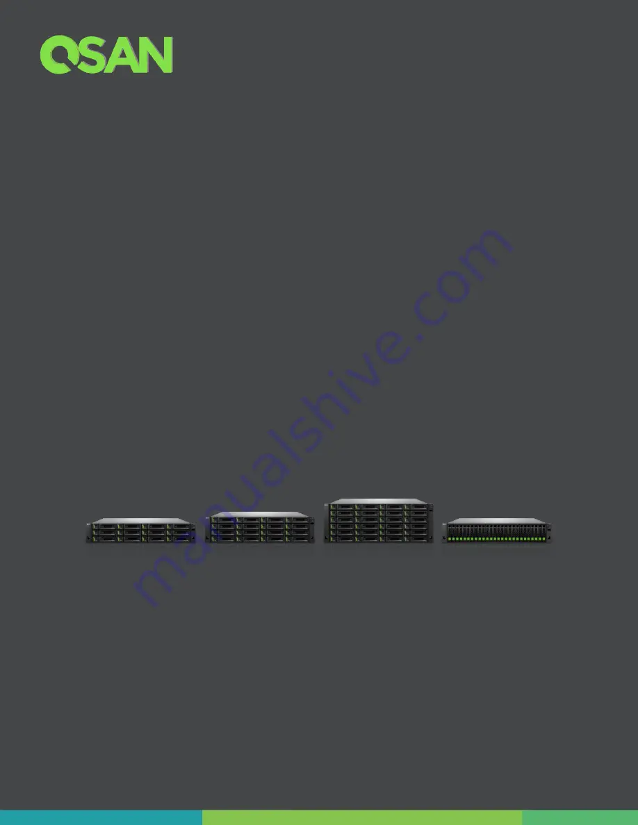
XCubeSAN Series 
Hardware Manual 


Applicable Models: 

XS5224D, XS5224S, XS5216D, XS5216S, XS5212D, XS5212S 
XS5226D, XS5226S, XS3224D, XS3224S, XS3216D, XS3216S 
XS3212D, XS3212S, XS3226D, XS3226S, XS1224D, XS1224S 
XS1216D, XS1216S, XS1212D, XS1212S, XS1226D, XS1226S 


QSAN Technology, Inc. 

www.QSAN.com 


Summary of Contents for XCubeSAN XS5224D

Page 1: ...cable Models XS5224D XS5224S XS5216D XS5216S XS5212D XS5212S XS5226D XS5226S XS3224D XS3224S XS3216D XS3216S XS3212D XS3212S XS3226D XS3226S XS1224D XS1224S XS1216D XS1216S XS1212D XS1212S XS1226D XS1...

Page 2: ...on is accurate as of its publication date The information is subject to change without notice Trademarks QSAN the QSAN logo XCubeSAN and QSAN com are trademarks or registered trademarks of QSAN Techno...

Page 3: ...2 2 System Disk Drive Numbering 16 2 3 Supported Disk Drives and SSDs 17 2 4 Rear Panel 18 2 4 1 Rear Panel Layout 18 2 4 2 Controller Module 20 2 5 Power Supply Unit 22 2 6 Fan Module 23 2 7 Cache to...

Page 4: ...4 2 3 Dual Path MPIO Deployment 70 4 2 4 Multi server Attached Cabling Deployment 72 4 2 5 Expansion Topology and Deployment 75 4 2 6 Introduction of Remote Replication 78 5 Descriptions of LEDs and...

Page 5: ...Contents iii Appendix 121 End User License Agreement EULA 121...

Page 6: ...Figure 3 2 Unlock and Open the Carrier Handle of a Disk Drive Tray LFF 31 Figure 3 3 Unlock and Open the Carrier Handle of a Disk Drive Tray SFF 31 Figure 3 4 Hold the Carrier Handle and Pull out the...

Page 7: ...igure 4 3 One Server One HBA Two Switches One XCubeSAN Dual Path 71 Figure 4 4 One Server One HBA One XCubeSAN One XCubeDAS Dual Path 72 Figure 4 5 Two Servers One HBA per Server One XCubeSAN Single P...

Page 8: ...iled Fan Module in the SANOS UI 104 Figure 6 13 Mechanical Components of the Fan Module 105 Figure 6 14 Procedures of Removing the Fan Module 106 Figure 6 15 Procedures of Installing the Fan Module 10...

Page 9: ...ble 2 11 Location of the Cache to Flash Module 26 Table 2 12 Protection Memory Capacity by Different Cache to Flash Module 28 Table 3 1 Installation Checklist 29 Table 3 2 Front Side Components of LFF...

Page 10: ...6 Descriptions of 4 port 16Gb Fibre Channel Host Card SFP LEDs 88 Table 5 7 Descriptions of 2 port 16Gb Fibre Channel Host Card SFP LEDs 89 Table 5 8 Descriptions of 2 port 25GbE iSCSI Host Card SFP28...

Page 11: ...Dual Controller LFF 16 disk 3U Chassis XS5216S Single Controller LFF 16 disk 3U Chassis XS3216D Dual Controller LFF 16 disk 3U Chassis XS3216S Single Controller LFF 16 disk 3U Chassis XS1216D Dual Con...

Page 12: ...results obtained in other operating environments may vary significantly Some measurements may have been made on development level systems and there is no guarantee that these measurements will be the...

Page 13: ...mbient Therefore consideration should be given to installing the equipment in an environment compatible with the maximum ambient temperature Tma specified by the manufacturer 2 Reduced Air Flow Instal...

Page 14: ...aken Access is through the use of a TOOL or lock and key or other means of security and is controlled by the authority responsible for the location Recommended operation temperature 0 40 31 99 103 99...

Page 15: ...can only be gained by service persons or by users who have been instructed about the reasons for the restrictions applied to the location and about any precautions that shall be taken Access is throu...

Page 16: ...s System hardware and peripheral product s 3 years limited warranty from date of original purchase Battery Backup Module or super capacitor module applies for cache to flash module 1 year limited warr...

Page 17: ...upgrade the equipment s components by yourself Doing so may violate your warranty and expose you to electric shock Refer all servicing to authorized service personnel Please always follow the instruct...

Page 18: ...INFORMATION INFORMATION provides useful knowledge definition or terminology for reference TIP TIP provides helpful suggestions for performing tasks more effectively CAUTION CAUTION indicates that fail...

Page 19: ...indicates that you can choose a b or nothing braces Indicates required or expected values Example a b indicates that you must choose either a or b vertical bar Indicates that you have a choice betwee...

Page 20: ......

Page 21: ...ront panel rear panel redundant power supply and fan modules cache to flash module by using battery backup module or super capacitor module and expansion slots for optional Fibre Channel or 10GbE 1GbE...

Page 22: ...224S Single Controller LFF 24 bay 4U Chassis XS3224D Dual Controller LFF 24 bay 4U Chassis XS3224S Single Controller LFF 24 bay 4U Chassis XS1224D Dual Controller LFF 24 bay 4U Chassis XS1224S Single...

Page 23: ...Chassis XS1226D Dual Controller SFF 26 bay 2U Chassis XS1226S Single Controller SFF 26 bay 2U Chassis 1 2 XCubeSAN Series Hardware Features The following is a list of the key hardware components and...

Page 24: ...ty SCM Super Capacitor Module flash module to protect up to 16GB memory per controller You can also use SSDs to boost your overall system speed If you purchase SATA SSDs for your dual controller XCube...

Page 25: ...J45 ports 4 x 1GbE iSCSI RJ45 ports Built in 2 x 10GBASE T iSCSI RJ45 ports Built in 1 x 1GbE management port Expansion Connectivity per Controller Built in 2 x 12Gb s SAS wide ports SFF 8643 internal...

Page 26: ...s 20Gb bandwidth 2 6Gb MUX board needed for 2 5 SATA drives in dual controller system Table 1 5 XS3200 Series Hardware Specifications Model name XS3224D Dual XS3224S Single XS3216D Dual XS3216S Single...

Page 27: ...16 3U 16 bay LFF XD5312 2U 12 bay LFF XD5326 2U 26 bay SFF Up to 4 expansion units using third party LFF 102 bay 12Gb SAS expansion enclosure Max Drives Supported 432 424 420 434 Dimension H x W x D 1...

Page 28: ...performance Host Connectivity per Controller Optional Host Cards at Slot 1 PCIe Gen3 x 8 2 x 32Gb FC SFP28 ports 4 x 16Gb FC SFP ports 2 x 16Gb FC SFP ports 2 x 25GbE iSCSI SFP28 ports 4 x 10GbE iSCSI...

Page 29: ...Flash module to protect all memory capacity Super capacitor module Flash module to protect up to 16GB memory per controller LCM LCD Module USB LCM optional Power Supply 770W 850W 1 1 redundant 80 PLUS...

Page 30: ...ct your nearest local reseller or visit QSAN official web site https qsan com location Table 1 7 XCubeSAN Series Accessories Model Name Picture Description Applied Models DIM D44GB DDR4 ECC 4GB Memory...

Page 31: ...ort 10GBASE T iSCSI Host Card RJ45 HQ 01G4T 4 port 1GBASE T iSCSI Host Card RJ45 RGBF32P0 32G Fibre Channel SFP28 Optical Transceiver GBC SFP 16Gb J 16G Fibre Channel SFP Optical Transceiver RGBE25P0...

Page 32: ...r connecting HBA or RAID card CBL 12SH150 SAS 12G Expansion Cable SFF 8644 to SFF 8644 1 5 Meters LCM U162 Portable USB LCM SLR RM3640 Slide Rail HDT 351 3 5 Disk Drive Tray XS5224 XS5216 XS5212 XS322...

Page 33: ...rted Disk Drives and SSDs Rear Panel Power Unit Fan Module Cache to Flash Module 2 1 Front Panel The XCubeSAN Series features a unique design the system controls and indicators is located on the right...

Page 34: ...icators Table 2 1 Descriptions of System Controls and Indicators Number Description 1 System Power Button LED 2 UID Unique Identifier Button LED 3 System Access LED 4 System Status LED 5 USB Port for...

Page 35: ...em Front Panel Components Number Description 1 System Left Ear 2 Disk Drive Tray 3 System Right Ear 4 The System Controls and Indicators Disk Drive Tray Indicators figures and the table below illustra...

Page 36: ...he XCubeSAN system disk drive numbering The disk drive numbering for LFF system starts from the top of first row in left column this kind of disk drive numbering rule helps to balance the system weigh...

Page 37: ...popular SAS HDDs and SAS SATA SSDs available in the market to ensure that you have the highest level of flexibility in choosing the most advanced HDDs or SSDs available from the manufacturers or purc...

Page 38: ...s to install optional SATA 6Gb MUX board and bracket for 2 5 disk drive tray model name HDM 251 Please contact a QSAN authorized reseller for details purchasing information 2 4 Rear Panel The followin...

Page 39: ...Unit 1 2 Fan Module 1 3 Slot for Cache to Flash Module Flash Module 4 Controller Module 15 5 Controller Module 2 6 Power Supply Unit 2 7 Fan Module 2 8 Slot for Cache to Flash Module Power Module INFO...

Page 40: ...f each port LED and host cards optional parts Figure 2 6 General View of the Controller Module Controller Status LED Dirty Cache LED Master Slave LED Unique Identifier LED Figure 2 7 Components of the...

Page 41: ...set admin s Password to 1234 7 Console cable NULL modem cable to connect from console port of the storage system to a RS 232 port on the management PC The console settings are on the following Baud ra...

Page 42: ...U systems and 2U systems are the same but the installation direction is different If you pull out the PSU from the system chassis for 4U 3U system the sticker on the PSU will be at down side for 2U sy...

Page 43: ...ord Connect 3 PSU Handle 4 PSU LED Indicator If you want to learn more about the related color and behavior of the PSU LED please refer to the chapter 5 2 Rear Panel section in the Descriptions of LED...

Page 44: ...021 QSAN Technology Inc All Right Reserved location and mechanical components of the fan module that is installed in the LFF and SFF system Figure 2 10 Location of Each Fan Module Installed in the LFF...

Page 45: ...2 7 Cache to Flash Memory Protection In the event of power loss the I O cache data stored in the volatile memory will be lost this can cause data inconsistency especially in database applications The...

Page 46: ...t 2021 QSAN Technology Inc All Right Reserved Figure 2 12 Location of the Cache to Flash Module Table 2 11 Location of the Cache to Flash Module Number Description 1 Slot for Flash Module 2 Slot for P...

Page 47: ...is the working sequence of QSAN Cache to Flash workflow Figure 2 15 Cache to Flash Workflow Cache to Flash technology will first flush CPU cache to memory RAM then flush memory RAM to M 2 flash module...

Page 48: ...lash module comes with a M 2 flash module and either a BBM or a SCM All modules are hot pluggable with zero system downtime for extra availability and reliability M 2 flash module can be plugged in on...

Page 49: ...the optional host cards Chapter 3 3 3 Installing the optional memory modules Chapter 3 4 4 Installing the optional cache to flash modules Chapter 3 5 5 Installing the optional slide rails Chapter 3 6...

Page 50: ...ing transport You must unlock disk drive trays before starting to install drives into the system chassis The following content is the detailed steps for removing a disk drive tray from the system Unlo...

Page 51: ...ck and Open the Carrier Handle of a Disk Drive Tray SFF The following content is the procedure for removing disk drive trays from the system Hold the carrier handle and pull the disk drive tray out un...

Page 52: ...32 Copyright 2021 QSAN Technology Inc All Right Reserved Figure 3 4 Hold the Carrier Handle and Pull out the Disk Drive Tray LFF Figure 3 5 Hold the Carrier Handle and Pull out the Disk Drive Tray SFF...

Page 53: ...r disk drive tray screw holes located on both sides of the hard drive Install and tighten all four screws to secure the disk drive within the tray Figure 3 6 Align a Disk Drive Install into a Tray LFF...

Page 54: ...y SFF to LFF For installing an SFF disk drive into an SFF tray Place a disk drive tray onto a stable surface Remove the supporting bracket Then align the disk drive with the connector facing away from...

Page 55: ...able below shows the available disk drive trays MUX board with bracket and their descriptions Table 3 3 Available Disk Drive Trays for XCubeSAN Series Model Name Picture Description Applied Models HDT...

Page 56: ...el host cards you can choose a iSCSI SAN by using 10GbE via SFP 10GBASE T or 1GBASE T iSCSI host cards The table below shows the available host card types model names and their descriptions Table 3 4...

Page 57: ...he system chassis before installing removing host card Please DO NOT attempt to hot plug in the host card Following figure is the overview of the host card installation slots Figure 3 9 Host Card Inst...

Page 58: ...F32P29 or HQ 16F4S29 or HQ 16F2S29 N A Dual Controller CTRL 1 RHCF32P2 or HQ 16F4S2 or HQ 16F2S2 Empty or RHCF32P29 or HQ 16F4S29 or HQ 16F2S29 CTRL 2 RHCF32P2 or HQ 16F4S2 or HQ 16F2S2 Empty or RHCF3...

Page 59: ...10G2T or HQ 01G4T Mix SAN 32 16Gb FC 25 10 1GbE Single Controller CTRL 1 RHCF32P2 or HQ 16F4S2 or HQ 16F2S2 RHCE25P29 or HQ 10G4S29 or HQ 10G2T or HQ 01G4T N A Dual Controller CTRL 1 RHCF32P2 or HQ 16...

Page 60: ...ATION Due to the total bandwidth of slot 2 is 20Gb It CAN NOT satisfy four ports of 10GbE iSCSI with full speed we strongly recommend combining two ports by enabling link aggregation for failover Such...

Page 61: ...e controller module from the system chassis Use a Phillips screwdriver to loosen the thumb screws on each release levers Pull down both levers at the same time and then pull out about half length of t...

Page 62: ...d Figure 3 11 Steps of Removing the Controller Module Remove the dummy host card cage by loosening two screws of the dummy host card cage and then take dummy host card cage from controller module Figu...

Page 63: ...are other host adapter cards need to be installed You must install GBIC s for the Fibre Channel or 10GbE host cards before connecting the cables from the storage system to the host sides Install the c...

Page 64: ...R4 for XS3200 XS1200 and 8GB DDR4 for XS5200 If you purchase additional optional memory module for your storage system please refer to the following image and table for the suggested sequence of memor...

Page 65: ...Memory Module DIM D432GB DDR4 ECC 32GB Memory Module XS5200 Series XS3200 Series In XS3200 and XS5200 there are four DIMM slots for expansion of memory capacity The installation sequence for the memor...

Page 66: ...2 Total Memory Slot 1 Slot 2 Slot 3 Slot 4 4GB 4GB 4GB 4GB 8GB 4GB 8GB 12GB 4GB 8GB 8GB 20GB 4GB 16GB 20GB 4GB 16GB 16GB 36GB 4GB 4GB 4GB 12GB 4GB 4GB 4GB 4GB 16GB 4GB 4GB 8GB 16GB 4GB 4GB 8GB 8GB 24...

Page 67: ...d the others are UDIMM The platform does not support mixing of DIMM so there are not allowed the combinations of mixing 32GB TIP Insert two DIMMs or more will boost performance In XS1200 there are two...

Page 68: ...ected power loss The table below is the available Cache to Flash module list If you want to purchase cache to flash module please contact your nearest local reseller or visit QSAN official web site ht...

Page 69: ...blinking Otherwise the flash module maybe damage For more information about Cache to Flash modules please refer to the chapter 5 2 4 Cache to Flash Module LEDs and Button section and the chapter 6 5...

Page 70: ...le Release Tab 2 Flash Module Attention Button 3 Flash Module Handle 4 Flash Module Status LED 5 Flash Module Power LED Power Module 6 Power Module Release Tab 7 Power Module Handle Remove the dummy c...

Page 71: ...h flash and power modules are facing left hand side while installing into the system 2U chassis release tabs of both flash and power modules are facing upward while installing into the system Figure 3...

Page 72: ...f you did not purchase QSAN qualified slide rails please skip this section The table below shows the available slide rail model name and its description Table 3 13 Available Slide Rails for XCubeSAN S...

Page 73: ...ll the disk drive trays into the system after the system chassis is mounted in the rack Doing this can reduce the loading of the overall weight when you mount the system chassis in the rack 1 First st...

Page 74: ...Figure 3 24 Second Step of the Slide Sails Installation 3 Third step of the slide rails installation Install the outer rail bracket assembly to the frame Repeat this installation step for the other si...

Page 75: ...e dedicated for optional slide rails are packed in the screws pack Figure 3 26 Fourth Step of the Slide Sails Installation 3 7 Installing the Trays into the System Before installing please check if th...

Page 76: ...tton Lock LFF Figure 3 28 Install a Tray into the System and Lock the Release Button Lock SFF 3 8 Connecting the System to a Host The XCubeSAN series products are equipped with two on board 10GbE iSCS...

Page 77: ...e cabling for the XCubeSAN management ports Figure 3 29 Cabling Example of the Administrator to the XCubeSAN Management Port 3 8 2 Dual Path MPIO Deployment The following images illustrate some exampl...

Page 78: ...er One HBA Two Switches One XCubeSAN Dual Path 3 8 3 Expansion Deployment One Server One HBA One XCubeSAN One XCubeDAS Dual Path The following figure shows an example of a dual controller connect encl...

Page 79: ...If you find the power cords included with your XCubeSAN system doesn t match your current country region you may need to buy an adapter for each power cord to connect the power outlet Power cord ratin...

Page 80: ...purchase must equal to or higher than the minimum requirement to ensure the system safety and reliability Figure 3 33 PSU Power Cord Connects INFORMATION The Following are the operational conditions...

Page 81: ...wering OFF the System To power off the system please follow the steps outlined below Stop all I O from all hosts to the SAN systems Shut down the SAN system by one of the methods that are described be...

Page 82: ...storage system is shut down for maintenance or other purposes Wake on SAS can avoid unnecessary electricity waste by allowing your devices to be on only when it is necessary A further advantage of Wak...

Page 83: ...to power on the attached XD5300 expansion enclosures Figure 3 36 Wake on LAN and Wake on SAS Technology 3 12 Connecting a UPS If users want to install a UPS uninterruptible power supply to provide cle...

Page 84: ...5 Available UPS Cable for XCubeSAN Series Model Name Picture Description Applied Models CBL UPS UPS Cable Phone jack 1 Meter XS5200 Series XS3200 Series XS1200 Series For checking the UPS connection a...

Page 85: ...XCubeSAN SANOS 4 0 Software Manual 3 14 Discover and Carry Out the Initial Configuration for the System After powering on the system the next step is to discover the system on the network and start t...

Page 86: ...the host server to the XCubeSAN system In this deployment only one controller in the enclosure is used Dual Path for dual controller models In a dual path deployment two paths are connected from the...

Page 87: ...table below shows the available cable model name and its description Table 4 2 The List of Available Cable for XCubeSAN Series Model Name Picture Description Applied Models CBL 12SW150 SAS 12G Expans...

Page 88: ...52 2 520TB 4 032TB 3rd Party 4U 102 bay LFF 4 12 4 x 10² 420 4 200TB 6 720TB XS5216 XS3216 XS1216 3U 16 bay LFF XD5312 2U 12 bay LFF 10 16 10 x 12 136 1 360TB 2 176TB XD5316 3U 16 bay LFF 10 16 10 x 1...

Page 89: ...60 266 2 462 4TB 4 239 36TB 3rd Party 4U 102 bay LFF 4 26 4 x 10² 434 4 142 4TB 6 927 36TB 4 2 2 Single Path Deployment The following images illustrate some examples of deployment types for single co...

Page 90: ...t The following images illustrate some examples of deployment types for dual controller XCubeSAN series MPIO MultiPath I O configurations are designed to provide HA High Availability data connections...

Page 91: ...a dual controller connect enclosure configuration with one server accessing the storage One server is connected to a dual controller XCubeSAN series using CAT 6 network cables And a dual controller X...

Page 92: ...ne HBA per Server One XCubeSAN Single Path The following figure shows an example of a single controller direct connect enclosure configuration with two servers accessing the storage Two servers are di...

Page 93: ...re shows an example of a dual controller connect enclosures configuration with two servers accessing the storage via switches Two servers are connected to a dual controller XCubeSAN series using CAT 6...

Page 94: ...shows an example of a dual controller direct connect enclosure configuration with ten servers accessing the storage Two servers connect to the on board 10GbE iSCSI RJ45 ports Eight servers connect to...

Page 95: ...scade Topology One XCubeSAN One XCubeDAS Dual Path The following figure shows an example of a dual controller XCubeSAN series connected to a dual controller XCubeDAS XD5300 series using mini SAS HD to...

Page 96: ...d to a dual controller XCubeDAS XD5300 series which is in turn connected to the second dual controller XCubeDAS XD5300 series using mini SAS HD to mini SAS HD cable SAS 12G expansion cable with Wake o...

Page 97: ...AS XD5300 series which is in turn connected to the second dual controller XCubeDAS XD5300 series using mini SAS HD to mini SAS HD cable SAS 12G expansion cable with Wake on SAS SFF 8644 to SFF 8644 Th...

Page 98: ...SFF 8644 Figure 4 11 Tree Topology One XCubeSAN Two XCubeDAS Dual Path INFORMATION Tree topology is available in SANOS firmware 1 1 0 4 2 6 Introduction of Remote Replication If users purchase two or...

Page 99: ...ote replication topology Bi Directional Figure 4 13 Bi Directional Remote Replication Each system in a two system topology acts as a replication target for the other s production data A Source Volume...

Page 100: ...D Many to One Figure 4 15 Many to One Remote Replication Multiple source systems replicate to a single target system A Source Volume S1 in Site B is replicating to a Target Volume T1 in Site A At the...

Page 101: ...that all supported topologies have a 1 to 1 configuration for each individual replication session in the topology The maximum replication task quantity per system is 32 It means that 32 systems are t...

Page 102: ...standing about the current status of the system or specific components by recognizing the LED status 5 1 Front Panel In this session we will describe the system controls and indicators and the disk dr...

Page 103: ...ress it again to turn it OFF UID Unique Identifier LED Press the button to turn it ON and press it again to turn it OFF Solid Blue The system has been identified Off The system has not been identified...

Page 104: ...ns of Disk Drive LEDs Number Description Definition 1 Disk Drive Power LED Solid Blue The disk drive is inserted and no data access Blinking Blue The disk drive is accessing data Off There is no disk...

Page 105: ...n Definition 1 Controller Status LED Solid Green Controller status is normal Solid Red System is booting or the controller is failed 2 Master Slave LED only for dual controllers Solid Green This is th...

Page 106: ...lease refer to the following content for definitions of the LED behaviors Figure 5 4 The Power Supply Unit LED Table 5 4 Descriptions of the Power Supply Unit LED Number Description Definition 1 PSU L...

Page 107: ...ption Definition 1 Activity LED Solid Green Asserted when the link is establish Link OK without I O Blinking Green Asserted when the link is established and packets are being transmitted along with an...

Page 108: ...een Asserted when the link is establish Link OK without I O Blinking Green Asserted when the link is established and packets are being transmitted along with any receive activity Access Off No link is...

Page 109: ...d when the link is establish Link OK without I O Blinking Green Asserted when the link is established and packets are being transmitted along with any receive activity Access Off No link is detected o...

Page 110: ...P28 LEDs Number Description Definition 1 Activity LED Blinking Green Asserted when the link is established and packets are being transmitted along with any receive activity Access Off No link is detec...

Page 111: ...mber Description Definition 1 Activity LED Blinking Green Asserted when the link is established and packets are being transmitted along with any receive activity Access Off No link is detected or link...

Page 112: ...st Card RJ45 LEDs Number Description Definition 1 Access LED Blinking Green Asserted when the link is established and packets are being transmitted along with any receive activity Access Off No link i...

Page 113: ...EDs Number Description Definition 1 Activity LED Blinking Green Asserted when the link is established and packets are being transmitted along with any receive activity Access Off No link is detected o...

Page 114: ...mber Interlaced Installing or removing the flash module Solid Amber The flash module is failed or wrong PCIe connection speed 3 Attention Button Used to prompt system that the flash module can be remo...

Page 115: ...nician Do not attempt to carry out any maintenance outside of those outlined in the following section of this guide System damage due to incorrect maintenance or FRU replacement can affect your produc...

Page 116: ...he dummy controller cage provided for the empty slot to ensure the proper system cooling If you see the system health becomes Controller Degraded in the SANOS UI Dashboard System Information or the co...

Page 117: ...odule Table 6 1 Mechanical Components of the Controller Module Number Description 1 Release Lever 2 Thumb Screw The following are detailed steps for removing the controller module from the system chas...

Page 118: ...odule The following content and images are the detail steps of installing the controller module into the system chassis Make sure the position of both release levers of the controller is at downward A...

Page 119: ...s from the time you have installed the controller module into the system chassis the status LED will show solid green color if controller module is successfully installed then the web UI will show fig...

Page 120: ...er module Recommended place for removing the controller module the system is in a well secured rack or on a stable surface If you see the System Health showing PSU Fault or the PSU LED shows solid or...

Page 121: ...cription 1 PSU Release Tab 2 PSU Handle Before removing the PSU disconnect the power cord from the wall outlet then remove the other end that is connected to the PSU The following are detailed steps o...

Page 122: ...ng are detailed steps of installing the PSU into the system chassis Use one hand to hold one end of the power supply unit the side with release tab and handle and the other hand hold the bottom of the...

Page 123: ...Health is Good and no warning message on the upper right side of the SANOS UI Figure 6 11 Screenshot of the PSU Successfully Installed in the SANOS UI 6 3 Removing Installing the Fan Module The stand...

Page 124: ...n module installing or removing is highly recommended Recommended place for installing removing a fan module the system is on the well secured rack or onto stable surface If you see the System Health...

Page 125: ...llowing details the steps of removing the fan module from the system chassis Hold the fan module handle first and then press the release tab Pull out the fan module around half of the total fan module...

Page 126: ...talling the fan module into the system chassis Use one hand to hold one end of the fan module the side with release tab and handle and the other hand hold the bottom of the module then align it with t...

Page 127: ...reenshot of the Fan Module Successfully Installed in the SANOS UI 6 4 Removing the Host Card If you encounter data connection problems from the host s side but you don t know which port or which host...

Page 128: ...disconnect the host card with the connector in the controller cage Pull the host card out until it is free from the controller cage Install the substitute host card The detailed steps of installing a...

Page 129: ...Navigate to the SANOS UI SYSTEM SETTINGS Power Cache to Flash and view the status of the power module or flash module If it shows Failed that means your power module or flash is not functioning corre...

Page 130: ...the flash module from the system chassis you must press the attention button until the flash module status LED finished blinking Otherwise the flash module maybe damage For more information about Cach...

Page 131: ...tton of flash module and pull it out until it is free from system chassis Install the substitute flash module The detailed steps of installing the flash module please refer to the chapter 3 5 Installi...

Page 132: ...free from system chassis Install the dummy cache to flash cage and then use a Phillips screw driver to tighten it To ensure proper cooling of the system please install all dummy cache to flash module...

Page 133: ...pport Service hours 09 30 02 00 Monday Friday UTC 8 Summer time 09 30 01 00 Via Email support qsan com Information to Collect Product name model or version and serial number Operating system name and...

Page 134: ...114 Copyright 2021 QSAN Technology Inc All Right Reserved Figure 7 1 Download Service Package in the SANOS UI...

Page 135: ...for QSAN support team The following procedure will help you to setup the serial console via the console cable that is enclosed in the shipping carton The following image is the appearance of the cons...

Page 136: ...r the connection is made INFORMATION For more information about terminal software please refer to HyperTerminal http www hilgraeve com hyperterminal PuTTY http www putty org 3 Here we first demonstrat...

Page 137: ...Support and Other Resources 117 Figure 7 4 The Procedures of Setup Serial Console by HyperTerminal 4 If you are using PuTTY instead please refer to below...

Page 138: ...118 Copyright 2021 QSAN Technology Inc All Right Reserved...

Page 139: ...lowing is the procedure to setup the connection for online support via TeamViewer 1 Please download the TeamViewer from following hyper link https www teamviewer com en download 2 Install TeamViewer 3...

Page 140: ...oviding documentation that meets and exceeds your expectations To help us improve the documentation email any errors suggestions or comments to docsfeedback qsan com When submitting your feedback incl...

Page 141: ...sive non transferable non distributable non assignable non sub licensable license to install and use the Product pursuant to the terms of this EULA Any right beyond this EULA will not be granted Intel...

Page 142: ...DAMAGES OR LIABILITIES WHATSOEVER INCLUDING BUT NOT LIMITED TO LOSS OF DATA INFORMATION REVENUE PROFIT OR BUSINESS ARISING OUT OF OR RELATING TO THE USE OR INABILITY TO USE THE PRODUCT OR OTHERWISE UN...

Page 143: ...ULA will be binding upon and will inure to User s successors and permitted assigns This EULA shall be governed by and constructed according to the laws of R O C Any disputes arising from or in connect...

Reviews: