background image

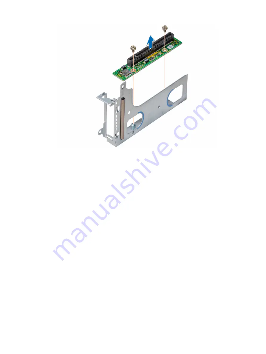
Figure 52. Removing the riser card

Next step

1

Install the riser card

.

Installing the riser card

Prerequisite

1

Follow the safety guidelines listed in 

Safety instructions

.

Steps

Place the riser card into the expansion card bracket.

Using the Phillips #2 screwdriver, tighten the screws that secure the riser card to the expansion card bracket.

Installing and removing enclosure components

105

Summary of Contents for PowerEdge C6420

Page 1: ...Dell EMC PowerEdge C6420 Installation and Service Manual Regulatory Model E43S Series Regulatory Type E43S001 ...

Page 2: ...age to hardware or loss of data and tells you how to avoid the problem WARNING A WARNING indicates a potential for property damage personal injury or death 2017 2019 Dell Inc or its subsidiaries All rights reserved Dell EMC and other trademarks are trademarks of Dell Inc or its subsidiaries Other trademarks may be trademarks of their respective owners 2019 04 Rev A03 ...

Page 3: ...tems 22 System battery 22 Expansion bus specifications 22 Memory specifications 23 Drives and storage specifications 23 Video specifications 24 Environmental specifications 24 Standard operating temperature specifications 24 Expanded operating temperature specifications 33 Particulate and gaseous contamination specifications 35 Maximum vibration specifications 36 Maximum shock specifications 36 Ma...

Page 4: ...side your system 63 Recommended tools 63 Dell EMC PowerEdge C6420 sled 64 Sled Installation Guidelines 64 Removing a sled 65 Installing a sled 67 PERC battery 69 Removing the PERC battery 69 Installing the PERC battery 70 Air shroud 71 Removing the air shroud 71 Installing the air shroud 72 System memory 73 System memory guidelines 73 General memory module installation guidelines 74 Removing a mem...

Page 5: ...r 107 Removing the M 2 SATA card 108 Installing the M 2 SATA card 109 M 2 SSD module 111 Removing the M 2 SATA x16 riser 111 Installing the M 2 SATA x16 riser 111 Removing the M 2 SATA card 112 Installing the M 2 SATA card 113 Mezzanine and OCP cards 115 Removing a mezzanine card 115 Installing a mezzanine card 116 Removing the mezzanine card bridge board 118 Installing the mezzanine card bridge b...

Page 6: ...er settings 131 System board connectors 132 Disabling forgotten password 133 9 Getting help 134 Contacting Dell EMC 134 Documentation feedback 134 Accessing system information by using QRL 134 Quick Resource Locator for C6400 and C6420 systems 135 Receiving automated support with SupportAssist 135 Recycling or End of Life service information 135 6 Contents ...

Page 7: ...connectivity NOTE The Intel Xeon Scalable processor with fabric connector is also known as Native Omnipath Topics Supported configurations Back view of the PowerEdge C6420 sled Network ports indicator codes Sled to hard drive mapping Expander zoning Locating the Service Tag of your system System information label Supported configurations The PowerEdge C6420 system supports the following configurat...

Page 8: ...Figure 1 Supported configurations for PowerEdge C6420 8 Dell EMC PowerEdge C6420 overview ...

Page 9: ...on cards For more information see the Technical specifications section 4 Sled release lock N A Enables you to remove the sled from the enclosure 5 Rear power button N A Enables you to power on the sled while accessing it from the rear 6 iDRAC or NIC port Enables you to remotely access iDRAC For more information see the Integrated Dell Remote Access Controller User s Guide at Dell com idracmanuals ...

Page 10: ...ress Service Code Service Tag and MAC address labels 11 System id indicator The System Identification ID LED is available on the back of the system Press the system ID button on the front of the enclosure to identify a system in a rack 12 USB 3 0 port 2 The USB ports are 9 pin and 3 0 compliant These ports enable you to connect USB devices to the system Network ports indicator codes Figure 3 LAN i...

Page 11: ...iBand Physical Link No Logical Link Green Off InfiniBand Logical Link No Traffic Green Green InfiniBand Logical Link Traffic Green Blink InfiniBand Physical Link Issue Blink Green Ethernet Link No Traffic Green Green Ethernet Traffic Green Blink NOTE The LED blink speed varies according to the traffic bandwidth Figure 5 Ethernet port indicator codes 1 speed indicator 2 link and activity indicator ...

Page 12: ...11 mapped to sled 2 3 Drives 12 17 mapped to sled 3 4 Drives 18 23 mapped to sled 4 5 Optional NVMe hard drive location Figure 7 Sled to drive mapping for the enclosure with 12 x 3 5 inch drives 1 Drives 0 2 mapped to sled 1 2 Drives 3 5 mapped to sled 2 3 Drives 6 8 mapped to sled 3 4 Drives 9 11 mapped to sled 4 NOTE The warranty of the drives are linked to the Service Tag of the corresponding s...

Page 13: ... Up to 6 SAS SATA device of each sled in Split Mode 6 6 6 6 Up to 12 SAS SATA device of sled 1 and sled 3 in Zoning Mode 12 12 Dell EMC PowerEdge C6420 overview 13 ...

Page 14: ...ervice Code and Service Tag number The Express Service Code and Service Tag are found on the back of the sled by pulling out the EST tag This information is used by Dell to route support calls to the appropriate personnel Figure 8 Locating the Service Tag of your system 1 information tag top view 2 Express Service Tag label 3 information tag bottom view 4 network MAC address information label 5 iD...

Page 15: ...System information label System board information Figure 9 System board connections Dell EMC PowerEdge C6420 overview 15 ...

Page 16: ...Mechanical overview Figure 10 Mechanical overview 16 Dell EMC PowerEdge C6420 overview ...

Page 17: ...Memory information Figure 11 Memory information Dell EMC PowerEdge C6420 overview 17 ...

Page 18: ...Jumper settings Figure 12 Jumper settings 18 Dell EMC PowerEdge C6420 overview ...

Page 19: ...the Getting Started Guide document that is shipped with your system Dell com poweredgemanuals Configuring your system For information about the iDRAC features configuring and logging in to iDRAC and managing your system remotely see the Integrated Dell Remote Access Controller User s Guide For information about understanding Remote Access Controller Admin RACADM subcommands and supported RACADM in...

Page 20: ...e Dell com serviceabilitytools For information about partner programs enterprise systems management see the OpenManage Connections Enterprise Systems Management documents Dell com openmanagemanuals Working with the Dell PowerEdge RAID controllers For information about understanding the features of the Dell PowerEdge RAID controllers PERC Software RAID controllers or BOSS card and deploying the car...

Page 21: ...orted operating systems System battery Expansion bus specifications Memory specifications Drives and storage specifications Video specifications Environmental specifications Dimensions of the Dell EMC PowerEdge C6420 sled Figure 13 Dimensions of the PowerEdge C6420 sled Table 5 Dimensions of the PowerEdge C6420 sled X Y Z 174 4 mm 6 86 inches 40 5 mm 1 59 inches 574 5 mm 22 61 inches 3 Technical s...

Page 22: ... Enterprise Server Microsoft Windows Server with Hyper V Canonical Ubuntu LTS VMware ESXi Citrix XenServer NOTE For more information about the specific versions and additions see https www dell com support home drivers supportedos poweredge c6420 System battery The PowerEdge C6420 sled uses a CR 2032 3V replaceable lithium coin cell battery NOTE There is a system battery in each of the sleds Expan...

Page 23: ...able 9 Supported drive options for the PowerEdge C6420 sled Maximum number of drives in the enclosure Maximum number of drives assigned per sled 12 x 3 5 inch drive systems Three SAS or SATA Drives and SSDs per sled 24 x 2 5 inch drive systems Six SAS or SATA Drives and SSDs per sled 24 x 2 5 inch drive systems with NVMe The NVMe backplane supports either of these configurations Two NVMe drives an...

Page 24: ...et located with the Manuals Documents on Dell com poweredgemanuals Standard operating temperature specifications NOTE 1 Not available Indicates that the configuration is not offered by Dell EMC 2 Not supported Indicates that the configuration is not thermally supported NOTE All components including the DIMMs communication cards M 2 SATA and PERC cards can be supported with sufficient thermal margi...

Page 25: ...D CPU1 6 CPU2 8 20 21 21 21 21 30 8280M CPU1 FMM2M CPU2 V2DRD CPU1 6 CPU2 8 20 21 21 21 21 30 8270 CPU1 FMM2M CPU2 V2DRD CPU1 6 CPU2 8 20 21 21 21 21 30 8268 CPU1 FMM2M CPU2 V2DRD CPU1 6 CPU2 8 20 21 21 21 21 30 200 W 6254 CPU1 FMM2M CPU2 V2DRD CPU1 6 CPU2 8 Not Suppor ted 6 C Not Suppo rted 1 4 C Not Supp orted 15 C 20 21 22 22 22 22 30 165 W 8276 CPU1 JYKMM CPU2 V2DRD CPU1 8 CPU2 8 Not Suppor te...

Page 26: ...150 W 6252 CPU1 JYKMM CPU2 V2DRD CPU1 8 CPU2 8 Not Suppor ted 14 C 21 23 30 30 30 30 30 35 35 6248 CPU1 JYKMM CPU2 V2DRD CPU1 8 CPU2 8 21 23 30 30 30 30 30 35 35 6240 CPU1 JYKMM CPU2 V2DRD CPU1 8 CPU2 8 21 23 30 30 30 30 30 35 35 6242 CPU1 JYKMM CPU2 V2DRD CPU1 8 CPU2 8 21 23 30 30 30 30 30 35 35 6244 CPU1 FMM2M CPU2 V2DRD CPU1 6 CPU2 8 21 23 30 30 30 30 30 35 35 6240C CPU1 FMM2M CPU2 V2DRD CPU1 6...

Page 27: ...35 35 35 6238T CPU1 JYKMM CPU2 V2DRD CPU1 8 CPU2 8 25 30 30 30 30 35 35 35 35 35 6230N CPU1 JYKMM CPU2 V2DRD CPU1 8 CPU2 8 25 30 30 30 30 35 35 35 35 35 115 W 5217 CPU1 FMM2M CPU2 V2DRD CPU1 6 CPU2 8 25 30 30 30 30 35 35 35 35 35 105 W 5218T CPU1 FMM2M CPU2 V2DRD CPU1 6 CPU2 8 30 35 35 35 35 35 35 35 35 35 5218N CPU1 FMM2M CPU2 V2DRD CPU1 6 CPU2 8 30 35 35 35 35 35 35 35 35 35 5222 CPU1 FMM2M CPU2...

Page 28: ...CPU2 V2DRD CPU1 8 CPU2 8 35 35 35 35 35 35 35 35 35 35 4215 CPU1 JYKMM CPU2 V2DRD CPU1 8 CPU2 8 35 35 35 35 35 35 35 35 35 35 4214 CPU1 JYKMM CPU2 V2DRD CPU1 8 CPU2 8 35 35 35 35 35 35 35 35 35 35 4214C CPU1 JYKMM CPU2 V2DRD CPU1 8 CPU2 8 35 35 35 35 35 35 35 35 35 35 4210 CPU1 JYKMM CPU2 V2DRD CPU1 8 CPU2 8 35 35 35 35 35 35 35 35 35 35 4208 CPU1 JYKMM CPU2 V2DRD CPU1 8 CPU2 8 35 35 35 35 35 35 3...

Page 29: ...0 35 35 35 35 35 35 35 200 W 6254 CPU1 FMM2M CPU1 6 30 30 30 35 35 35 35 35 35 35 165 W 6212U CPU1 JYKMM CPU1 8 30 35 35 35 35 35 35 35 35 35 8276 CPU1 JYKMM CPU1 8 30 35 35 35 35 35 35 35 35 35 8276L CPU1 JYKMM CPU1 8 30 35 35 35 35 35 35 35 35 35 8276M CPU1 JYKMM CPU1 8 30 35 35 35 35 35 35 35 35 35 8260 CPU1 JYKMM CPU1 8 30 35 35 35 35 35 35 35 35 35 8260L CPU1 JYKMM CPU1 8 30 35 35 35 35 35 35...

Page 30: ...18B CPU1 JYKMM CPU1 8 35 35 35 35 35 35 35 35 35 35 8253 CPU1 JYKMM CPU1 8 35 35 35 35 35 35 35 35 35 35 6238T CPU1 JYKMM CPU1 8 35 35 35 35 35 35 35 35 35 35 6230N CPU1 JYKMM CPU1 8 35 35 35 35 35 35 35 35 35 35 115 W 5217 CPU1 FMM2M CPU1 6 30 35 35 35 35 35 35 35 35 35 105 W 5218T CPU1 FMM2M CPU1 6 30 35 35 35 35 35 35 35 35 35 5218N CPU1 FMM2M CPU1 6 30 35 35 35 35 35 35 35 35 35 5222 CPU1 FMM2...

Page 31: ...x Navi Dual Port Card with Active Optical connectivity TDP Watts 3 5 inch chassis 2 5 inch chassis No BP Chassis 12x HDDs 8x HDDs 4x HDDs 24x HDDs 16x HDDs 8x HDDs 4x HDDs N A 205 W Not supported Not supported Not supported Not supported Not supported Not supported Not supported 23 200 W Not supported Not supported Not supported Not supported Not supported Not supported Not supported 23 173 W Not ...

Page 32: ...ed 20 20 23 200 W Not supported Not supported Not supported Not supported Not supported 21 21 24 173 W Not supported Not supported Not supported 20 20 23 24 28 165 W Not supported Not supported Not supported 22 22 24 25 29 160 W Not supported Not supported Not supported 22 22 24 26 29 150 W Not supported Not supported Not supported 24 24 26 27 30 140 W Not supported Not supported Not supported 26 ...

Page 33: ... supported Not supported Not supported Not supported Not supported 25 150 W Not supported Not supported Not supported Not supported 20 20 20 25 140 W Not supported Not supported Not supported 20 20 20 20 25 135 W Not supported Not supported Not supported 20 20 20 20 25 130 W Not supported Not supported Not supported 20 20 20 20 25 125 W Not supported Not supported Not supported 20 25 25 25 30 115 ...

Page 34: ...mperature range system performance may be impacted NOTE When operating in the expanded temperature range ambient temperature warnings may be reported in the System Event Log Operating temperature derating specifications Table 19 Operating temperature Operating temperature derating Specifications 35 C 95 F Maximum temperature is reduced by 1 C 300 m 1 F 547 ft above 950 meters 3 117 ft 35 C 40 C 95...

Page 35: ...nfidence limit NOTE This condition applies only to data center environments Air filtration requirements do not apply to IT equipment designed to be used outside a data center in environments such as an office or factory floor NOTE Air entering the data center must have MERV11 or MERV13 filtration Conductive dust Air must be free of conductive dust zinc whiskers or other conductive particles NOTE T...

Page 36: ...x y z axis for up to 11 ms four pulses on each side of the system Storage Six consecutively executed shock pulses of 71 G in the positive and negative x y z axes for up to 2 ms one pulse on each side of the system Maximum altitude specifications Table 26 Maximum altitude specifications Maximum altitude Specifications Operating 3048 m 10 000 ft Storage 12 000 m 39 370 ft Fresh Air Operation Fresh A...

Page 37: ...ted NVMe SSD is not supported AEP DIMM and LRDIMM are not supported PCIe cards greater than 25 W are not supported H730 PERC and H330 support for 105 W processors No PERC restrictions for 85 W and lesser TDP processors Technical specifications 37 ...

Page 38: ...he system Options to set up iDRAC IP address To enable communication between your system and iDRAC you must first configure the network settings based on your network infrastructure NOTE For static IP configuration you must request for it at the time of purchase This option is set to DHCP by Default You can set up the IP address by using one of the following interfaces Interfaces Document Section ...

Page 39: ...emote Access Controller User s Guide at Dell com poweredgemanuals You can also access iDRAC by using RACADM For more information see the RACADM Command Line Interface Reference Guide at Dell com poweredgemanuals Options to install the operating system If the system is shipped without an operating system install a supported operating system by using one of the following resources Table 27 Resources...

Page 40: ...cmanuals Downloading drivers and firmware Dell EMC recommends that you download and install the latest BIOS drivers and systems management firmware on your system Prerequisite Ensure that you clear the web browser cache before downloading the drivers and firmware Steps 1 Go to Dell com support home 2 In the Drivers Downloads section type the Service Tag of your system in the Enter a Service Tag or...

Page 41: ...onfigure the BIOS settings iDRAC settings and device settings of your system NOTE Help text for the selected field is displayed in the graphical browser by default To view the help text in the text browser press F1 You can access system setup by one of the following Standard graphical browser The browser is enabled by default Text browser The browser is enabled by using Console Redirection Viewing...

Page 42: ...f the operating system begins to load before you press F2 wait for the system to finish booting and then restart the system and try again 3 On the System Setup Main Menu screen click System BIOS System BIOS Settings details The System BIOS Settings screen details are explained as follows Option Description System Information Provides information about the system such as the system model name BIOS ...

Page 43: ...ange the system date and time System Information You can use the System Information screen to view system properties such as Service Tag system model name and BIOS version Viewing System Information To view the System Information screen perform the following steps 1 Power on or restart your system 2 Press F2 immediately after you see the following message F2 System Setup NOTE If your operating sys...

Page 44: ...wait for the system to finish booting and then restart the system and try again 3 On the System Setup Main Menu screen click System BIOS 4 On the System BIOS screen click Memory Settings Memory Settings details The Memory Settings screen details are explained as follows Option Description System Memory Size Specifies the memory size in the system System Memory Type Specifies the type of memory ins...

Page 45: ...c functions such as enabling virtualization technology hardware prefetcher logical processor idling and opportunistic self refresh Viewing Processor Settings To view the Processor Settings screen perform the following steps 1 Power on or restart your system 2 Press F2 immediately after you see the following message F2 System Setup NOTE If your operating system begins to load before you press F2 wa...

Page 46: ...e Nominal Level 1 and Level 2 This option is set to Nominal by default NOTE This option is only available on certain stock keeping units SKUs of the processors SST Performance Profile Enables you to reconfigure the processor using Speed Select Technology x2APIC Mode Enables or disables the x2APIC mode This option is set to Disabled by default Dell Controlled Turbo Controls the turbo engagement Thi...

Page 47: ...k Enables you to send Security Freeze Lock command to the embedded SATA drives during POST This option is applicable only for AHCI mode This option is set to Enabled by default Write Cache Enables or disables the command for the embedded SATA drives during POST This option is set to Disabled by default Port n Enables you to set the drive type of the selected device For AHCI Mode or RAID Mode BIOS ...

Page 48: ...irmware The interface consists of data tables with platform related information boot and runtime service calls that are available to the operating system and its loader The following benefits are available when the Boot Mode is set to UEFI Support for drive partitions larger than 2 TB Enhanced security e g UEFI Secure Boot Faster boot time NOTE You must use only the UEFI boot mode in order to boot...

Page 49: ...ngs Enables or disables BIOS boot options NOTE This option is enabled only if the boot mode is BIOS Generic USB Boot Enables or disables the USB boot option This option is set to Disabled by default Hard disk Drive Placeholder Enables or disables the Hard disk drive placeholder option This option is set to Disabled by default UEFI Boot Settings Enables or disables UEFI Boot options The UEFI option...

Page 50: ...iately after you see the following message F2 System Setup NOTE If your operating system begins to load before you press F2 wait for the system to finish booting and then restart your system and try again 3 On the System Setup Main Menu screen click System BIOS 4 On the System BIOS screen click Network Settings Network Settings screen details The Network Settings screen details are explained as fo...

Page 51: ...d by default iSCSI Device1 Settings Enables you to control the configuration of the iSCSI device Integrated Devices You can use the Integrated Devices screen to view and configure the settings of all integrated devices including the video controller integrated RAID controller and the USB ports Viewing Integrated Devices To view the Integrated Devices screen perform the following steps 1 Power on o...

Page 52: ...t State of Embedded Video Controller Displays the current state of the embedded video controller The Current State of Embedded Video Controller option is a read only field If the Embedded Video Controller is the only display capability in the system that is no add in graphics card is installed then the Embedded Video Controller is automatically used as the primary display even if the Embedded Vide...

Page 53: ...ables you to set the port address for serial device This field sets the serial port address to either COM1 or COM2 COM1 0x3F8 COM2 0x2F8 NOTE You can use only Serial Device 2 for the Serial Over LAN SOL feature To use console redirection by SOL configure the same port address for console redirection and the serial device NOTE Every time the system boots the BIOS syncs the serial MUX setting saved ...

Page 54: ...ets the CPU power management This option is set to System DBPM DAPC by default DBPM is Demand Based Power Management Other options include OS DBPM and Maximum Performance Memory Frequency Sets the speed of the system memory You can select Maximum Performance Maximum Reliability or a specific speed This option is set to Maximum Performance by default Turbo Boost Enables or disables the processor to...

Page 55: ...d by default PCI ASPM L1 Link Power Management Enables or disables the PCI ASPM L1 Link Power Management This option is set to Enabled by default System Security You can use the System Security screen to perform specific functions such as setting the system password setup password and disabling the power button Viewing System Security To view the System Security screen perform the following steps ...

Page 56: ...es you to set the time that the system should take to power up after AC power is restored to the system This option is set to Immediate by default User Defined Delay 60 s to 600 s Enables you to set the User Defined Delay option when the User Defined option for AC Power Recovery Delay is selected UEFI Variable Access Provides varying degrees of securing UEFI variables When set to Standard the defa...

Page 57: ... the Secure Boot Custom Policy To enable this option set the Secure Boot Policy to Custom Creating a system and setup password Prerequisite Ensure that the password jumper is enabled The password jumper enables or disables the system password and setup password features For more information see the System board jumper settings section NOTE If the password jumper setting is disabled the existing sy...

Page 58: ...or change an existing system or setup password if the Password Status is set to Locked Steps 1 To enter System Setup press F2 immediately after turning on or restarting your system 2 On the System Setup Main Menu screen click System BIOS System Security 3 On the System Security screen ensure that Password Status is set to Unlocked 4 In the System Password field change or delete the existing system...

Page 59: ... view the Redundant OS Control screen perform the following steps 1 Power on or restart your system 2 Press F2 immediately after you see the following message F2 System Setup NOTE If your operating system begins to load before you press F2 wait for the system to finish booting and then restart your system and try again 3 On the System Setup Main Menu screen click System BIOS 4 On the System BIOS s...

Page 60: ...ined as follows Option Description System Time Enables you to set the time on the system System Date Enables you to set the date on the system Asset Tag Specifies the asset tag and enables you to modify it for security and tracking purposes Keyboard NumLock Enables you to set whether the system should boot with the NumLock enabled or disabled This option is set to On by default NOTE This option do...

Page 61: ...osis LC is delivered as part of the iDRAC out of band solution and Dell system embedded Unified Extensible Firmware Interface UEFI applications Embedded system management The Dell Lifecycle Controller provides advanced embedded system management throughout the lifecycle of the system The Dell Lifecycle Controller can be started during the boot sequence and can function independently of the operati...

Page 62: ...aunch Lifecycle Controller Exits the Boot Manager and invokes the Dell Lifecycle Controller program System Utilities Enables you to launch System Utilities menu such as System Diagnostics and UEFI shell One shot UEFI boot menu One shot UEFI boot menu enables you to select a boot device to boot from System Utilities System Utilities contains the following utilities that can be launched Launch Diagn...

Page 63: ...r product NOTE It is recommended that you always use an antistatic mat and antistatic strap while working on components inside the system CAUTION To ensure proper operation and cooling all bays in the system and system fans must be always populated with a component or a blank Before working inside your system Prerequisite Follow the safety guidelines listed in Safety instructions Steps 1 Power off...

Page 64: ...l EMC PowerEdge C6420 sled Sled Installation Guidelines NOTE Ensure to install a sled blank in all the empty slots Operating the enclosure without a blank results in overheating NOTE For optimized thermal operation ensure to follow the sled population sequence mentioned below 64 Installing and removing enclosure components ...

Page 65: ...fety Instructions NOTE For optimized thermal performance see Sled installation guidelines NOTE The procedure to remove a sled blank or a sled are the same Step Press the retaining latch and using the sled pull handle slide the sled out of the enclosure horizontally Installing and removing enclosure components 65 ...

Page 66: ...le it is being slid out Figure 15 Removing a sled CAUTION If you are permanently removing the sled install a sled blank promptly Operating the enclosure without a blank for an extended time can result in overheating 66 Installing and removing enclosure components ...

Page 67: ... Safety Instructions NOTE For optimized thermal performance see Sled installation guidelines Step Slide the sled into the enclosure horizontally ensuring that the sled is supported from beneath until it locks into place NOTE To avoid any damages to the pins on the sled do not force the sled into the enclosure Installing and removing enclosure components 67 ...

Page 68: ...Figure 17 Installing a sled 68 Installing and removing enclosure components ...

Page 69: ...ow the procedure listed in Before working inside your enclosure 3 Remove the sled from the enclosure 4 If applicable disconnect the battery cable from the PERC card CAUTION Do not hold the battery cable and lift the battery out Step Holding the cable end of the battery lift the battery out of the air shroud Installing and removing enclosure components 69 ...

Page 70: ...ctions 2 Follow the procedure listed in After working inside your enclosure 3 Install the sled from the enclosure 4 If applicable connect the battery cable from the PERC card Steps 1 Align and insert the non cable end of the PERC battery into the battery slot on the air shroud 2 Press the battery until it locks into place 70 Installing and removing enclosure components ...

Page 71: ...uisites 1 Follow the safety guidelines listed in Safety instructions 2 Follow the procedure listed in Before working inside your enclosure 3 If applicable disconnect the battery cable from the PERC card Steps 1 Press the clip on the air shroud to release the shroud from the sled 2 Remove the shroud by rotating the shroud and releasing the hinge from the slot on the system Installing and removing e...

Page 72: ...t the air shroud into the sled aligning the shroud hinge with slot on the sled NOTE Ensure that both the SATA cables are routed through the air shroud cable guide slot behind the air shroud latches NOTE Ensure that neither of the cables are pinched or pressed under the air shroud 2 Press the air shroud until the locks click into place 72 Installing and removing enclosure components ...

Page 73: ...s RDIMMs and load reduced DIMMs LRDIMMs System memory holds the instructions that are executed by the processor Your system contains 16 memory sockets split into two sets of 8 sockets one set per processor Each 8 socket set is organized into channels In each channel the release tabs of the first socket are marked white the second socket black Figure 23 Memory socket locations Memory channels are o...

Page 74: ...m of two different ranked DIMMs can be populated in a channel regardless of rank count If memory modules with different speeds are installed they will operate at the speed of the slowest installed memory module s Populate memory module sockets only if a processor is installed For single processor systems sockets A1 to A8 are available For dual processor systems sockets A1 to A8 and sockets B1 to B...

Page 75: ...annel while the operating system is running they are moved to the spare area to prevent errors from causing an uncorrectable failure Requires two or more ranks to be populated in each channel Multi Rank Spare Mode Multi Rank Spare Mode allocates two ranks per channel as a spare If excessive correctable errors occur in a rank or channel while the operating system is running they are moved to the sp...

Page 76: ...ocessor Start with processor1 processor1 and processor 2 population should match Optimized Independent channel population order A 1 B 1 A 2 B 2 A 4 B 4 A 5 B 5 Odd amount of DIMMs per processor allowed Mirroring population order A 1 2 3 4 5 6 B 1 2 3 4 5 6 Mirroring is supported with 6 DIMMs per processor Single rank sparing population order A 1 B 1 A 2 B 2 A 3 B 3 Populate in this order odd amoun...

Page 77: ...you are removing the memory module permanently install a memory module blank The procedure to install a memory module blank is similar to that of the memory module Installing a memory module Prerequisite 1 Follow the safety guidelines listed in Safety instructions Steps 1 Locate the appropriate memory module socket CAUTION Handle each memory module only by the edges ensuring not to touch the middl...

Page 78: ...tings In the Memory Settings screen the System Memory Size must reflect the updated capacity of the installed memory 4 If the value is incorrect one or more of the memory modules may not be installed properly Ensure that the memory module is firmly seated in the memory module socket 5 Run the system memory test in system diagnostics Support bracket Removing the support bracket Prerequisites 1 Foll...

Page 79: ...Installing the support bracket Prerequisite 1 Follow the safety guidelines listed in Safety instructions Steps 1 Place the support bracket in the sled 2 Using a Phillips 1 screwdriver replace the screws to secure the bracket in place Installing and removing enclosure components 79 ...

Page 80: ...n Safety instructions 2 Follow the procedure listed in Before working inside your enclosure 3 Remove the air shroud 4 Remove the support bracket Steps 1 Press the release clip on the PCIe_A cable connector to disconnect the cable See the System board connector for more information 2 Press the release clip on the PCIe_B cable connector to disconnect the cable See the System board connector for more...

Page 81: ... Follow the safety guidelines listed in Safety instructions Steps 1 Insert the PCIe_A connector into the connector on the system board press the connector until it locks into place 2 Insert and press the PCIe_B connector into the connector on the system board press the connector until it locks into place 3 If disconnected reconnect the SATA cable to the x16 M 2 riser 4 Using the Phillips 1 screwdr...

Page 82: ...on fabric processor installed in the CPU1 socket you must connect the external Omnipath link cables to Port 2 on the OCP carrier card Use the following procedure when Removing and installing a heat sink Replacing a processor Table 35 Supported heat sinks Heat sink Dimensions Design CPU 1 standard heat sink Length 108 mm 4 25 inches Width 88 mm 3 46 inches Height 24 8 mm 0 97 inches 2 heat pipes CP...

Page 83: ...led disconnect the fabric cable from the fabric processor NOTE The process to remove a processor heat sink module PHM is identical for a fabric and a nonfabric processor Steps 1 Using a Torx T30 screwdriver loosen the screws on the heat sink in the order mentioned below a Loosen the first screw three turns b Loosen the second screw completely c Return to the first screw and loosen it completely 2 ...

Page 84: ...cessor unless you intend to replace the processor The heat sink is necessary to maintain proper thermal conditions 1 Follow the safety guidelines listed in Safety instructions 2 If installed remove the CPU dust cover Steps 1 Align the pin 1 indicator of the heat sink to the system board and then place the processor and heat sink module PHM on the processor socket 84 Installing and removing enclosu...

Page 85: ...tely c Return to the first screw and tighten it completely If the PHM slips off the blue retention clips when the screws are partially tightened follow these steps to secure the PHM a Loosen both the heat sink screws completely b Lower the PHM on to the blue retention clips following the procedure described in step 2 c Secure the PHM to the system board following the replacement instructions liste...

Page 86: ...procedure listed in Before working inside your enclosure 3 Remove the air shroud 4 Remove the fabric cable from the processor 5 Remove the processor and heat sink module Steps 1 Place the heat sink with the processor contact side facing up 2 Insert the flat blade screwdriver into the release slot and twist do not pry the screwdriver to break the seal created by the thermal paste 3 Push the retaini...

Page 87: ... the safety guidelines listed in Safety instructions Steps 1 Ensure that the processor is in the CPU tray NOTE Ensure that pin 1 indicator on the CPU tray is aligned with the pin 1 indicator on the processor 2 Flex the outer edges of the bracket around the processor close to the fabric connector ensuring that the processor is locked into the clips on the bracket 3 Press the other end of the bracke...

Page 88: ...ermal grease can result in excess grease coming in contact with and contaminating the processor socket 5 Use the thermal grease syringe included with your processor kit to apply the grease in a quadrilateral design on the top of the processor NOTE The thermal grease syringe is intended for single use only Dispose the syringe after you use it 88 Installing and removing enclosure components ...

Page 89: ... NOTE Ensure that the two guide pin holes on the bracket match the guide holes on the heat sink Ensure that the pin 1 indicator on the heat sink is aligned with the pin 1 indicator on the bracket before placing the heat sink on the processor and bracket Figure 36 Installing the heat sink onto the processor Installing and removing enclosure components 89 ...

Page 90: ...d 1 Follow the safety guidelines listed in Safety instructions 2 Follow the procedure listed in Before working inside your enclosure 3 Remove the air shroud 4 Remove the processor and heat sink module Steps 1 Place the heat sink with the processor side facing up 2 Insert a flat blade screwdriver into the release slot marked with a yellow label Twist do not pry the screwdriver to break the thermal ...

Page 91: ...r away from the heat sink and place the processor connector side down on the processor tray 5 Flex the outer edges of the bracket to release the bracket from the processor NOTE Ensure that the processor and the bracket are placed in the tray after you remove the heat sink Installing and removing enclosure components 91 ...

Page 92: ...bles to Port 2 on the OCP carrier card Follow the safety guidelines listed in Safety instructions Steps 1 Place the processor in the processor tray NOTE Ensure that the pin 1 indicator on the processor tray is aligned with the pin 1 indicator on the processor 2 Flex the outer edges of the bracket around the processor ensuring that the processor is locked into the clips on the bracket NOTE Ensure t...

Page 93: ...ssor kit to apply the grease in a quadrilateral design on the top of the processor CAUTION Applying too much thermal grease can result in excess grease coming in contact with and contaminating the processor socket NOTE The thermal grease syringe is intended for single use only Dispose the syringe after you use it Figure 42 Applying thermal grease on top of the processor Installing and removing enc...

Page 94: ... on the heat sink fins Ensure that the pin 1 indicator on the heat sink is aligned with the pin 1 indicator on the bracket before placing the heat sink onto the processor and bracket Figure 43 Installing the heat sink onto the processor Next steps 1 Install the processor and heat sink module 2 Install the air shroud 3 Follow the procedure listed in After working inside your enclosure 94 Installing...

Page 95: ...e the fabric connector pull the connector away from the processor 3 Pressing the connector clips release the side band cable from the connector and lift the cable away Figure 44 Removing the fabric and sideband cables Next step 1 Install the fabric and sideband cables Installing the fabric and sideband cables Prerequisites NOTE In a sled which has been configured with mixed CPUs a fabric processor...

Page 96: ...r down to secure the fabric connector in place 4 Insert the side band cable into the respective connector and press down to lock the connector Figure 45 Installing the fabric and sideband cables Next steps 1 Install the air shroud 2 Follow the procedure listed in After working inside your enclosure Expansion cards NOTE A missing or an unsupported expansion card riser logs an System Event Log SEL e...

Page 97: ...ifications Table 37 Supported expansion cards Card type Form factor Link width Slot priority Maximum number of cards Intel Kerby Flat mezzanine network card Mezzanine x8 3 1 Broadcom 25G SFP network card Mezzanine x8 3 1 H730P Mini controller card Mezzanine x8 1 1 H330 SAS controller adapter Mezzanine x8 1 1 HBA330 MINI controller adapter Mezzanine x8 1 1 12 GB SAS LPF HBA controller adapter LP x8...

Page 98: ... 1 SF80X 10G dual port network card LP x8 4 1 Intel 10G Base T quad port network card LP x8 4 1 Intel 1 GB dual port V3 network card LP x4 4 1 Intel 10G dual port SFP V2 network card LP x8 4 1 Broadcom 1G dual port network card LP x1 4 1 QLogic 10G dual port network card LP x8 4 1 QLogic 10G dual port V2 network card LP x8 4 1 QLogic 10G dual port SFP network card LP x8 4 1 QLogic 10G dual port SF...

Page 99: ...in Federal Communications Commission FCC certification of the system The brackets also keep dust and dirt out of the system and aid in proper cooling and airflow inside the system 1 Follow the safety guidelines listed in Safety instructions 2 Follow the procedure listed in Before working inside your enclosure Steps 1 Remove the screws that secure the expansion card riser assembly 2 Lift the expans...

Page 100: ...ure the expansion card riser assembly Figure 47 Installing the expansion card riser assembly Next step 1 Follow the procedure listed in After working inside your enclosure Removing an expansion card Prerequisites 1 Follow the safety guidelines listed in Safety instructions 2 Follow the procedure listed in Before working inside your enclosure 3 Remove the expansion card riser assembly Steps 1 Remov...

Page 101: ...Figure 48 Removing an expansion card Installing and removing enclosure components 101 ...

Page 102: ... bracket by performing the following steps a Remove the screw that secures the filler bracket b Hold the filler bracket by its edges and carefully remove it from the riser card NOTE You must install an expansion card filler bracket over an empty expansion slot to maintain Federal Communications Commission FCC certification of the system The brackets also keep dust and dirt out of the system and ai...

Page 103: ...Figure 50 Removing the expansion card filler bracket Installing and removing enclosure components 103 ...

Page 104: ...y guidelines listed in Safety instructions 2 Follow the procedure listed in Before working inside your enclosure 3 Remove the expansion card riser assembly 4 If installed remove the expansion card Steps 1 Using the Phillips 2 screwdriver remove the screws that secure the riser card to the expansion card bracket 2 Lift the riser card away from the expansion card bracket 104 Installing and removing ...

Page 105: ... Prerequisite 1 Follow the safety guidelines listed in Safety instructions Steps 1 Place the riser card into the expansion card bracket 2 Using the Phillips 2 screwdriver tighten the screws that secure the riser card to the expansion card bracket Installing and removing enclosure components 105 ...

Page 106: ... x16 riser Prerequisites 1 Follow the safety guidelines listed in Safety instructions 2 Follow the procedure listed in Before working inside your enclosure Steps 1 Using the Phillips 1 screwdriver loosen the screw that secures the riser to the sled 2 Lift the riser up to disengage the riser from the connector on the system board 3 Disconnect the data cable from the riser 106 Installing and removin...

Page 107: ... listed in Safety instructions Steps 1 Connect the data cable to the riser 2 Insert the keyed end of the M 2 SATA riser into the lock on the system board 3 Align and insert the edge connector into the connector on the system board 4 Using the Phillips 2 screwdriver tighten the screw to secure the riser to the sled Installing and removing enclosure components 107 ...

Page 108: ...e working inside your enclosure 3 If applicable remove the expansion card riser assembly 4 Remove the M 2 x16 riser or install the M 2 SATA x8 mezzanine card NOTE The procedure to remove the M 2 SATA x8 mezzanine card is similar to removing a mezzanine card Steps 1 Using the Phillips 1 screwdriver unscrew the screw that secures the M 2 card to the board 2 Pull the card out of the connector and lif...

Page 109: ... riser Figure 57 Removing the M 2 SATA card from the x8 mezzanine card Next step 1 Install the M 2 SATA card Installing the M 2 SATA card Prerequisite 1 Follow the safety guidelines listed in Safety instructions Installing and removing enclosure components 109 ...

Page 110: ...er Figure 59 Installing the M 2 SATA card on the SATA x8 mezzanine card Next steps 1 If removed install the expansion card riser assembly 2 Install the M 2 x16 riser or install the M 2 SATA x8 mezzanine card NOTE The procedure to install the M 2 SATA x8 mezzanine card is similar to installing a mezzanine card 3 Follow the procedure listed in After working inside your enclosure 110 Installing and r...

Page 111: ... in Safety instructions 2 Follow the procedure listed in Before working inside your enclosure 3 Remove the sled from the enclosure Steps 1 Using the Phillips 1 screwdriver loosen the screw that secures the riser to the sled 2 Lift the riser up to disengage the riser from the connector on the system board 3 Disconnect the data cable from the riser Figure 60 Removing the M 2 SATA x16 riser Next step...

Page 112: ...closure Removing the M 2 SATA card Prerequisites 1 Follow the safety guidelines listed in Safety instructions 2 Follow the procedure listed in Before working inside your enclosure 3 Remove the sled from the enclosure 4 If applicable remove the expansion card riser assembly 5 Remove the M 2 x16 riser or the M 2 SATA x8 mezzanine card NOTE The procedure to remove the M 2 SATA x8 mezzanine card is si...

Page 113: ...6 riser Figure 63 Removing the M 2 SATA card from the x8 mezzanine card Next step Install the M 2 SATA card Installing the M 2 SATA card Prerequisite 1 Follow the safety guidelines listed in Safety instructions Installing and removing enclosure components 113 ...

Page 114: ...nstalling the M 2 SATA card on the SATA x8 mezzanine card Next steps 1 If removed install the expansion card riser assembly 2 Install the M 2 x16 riser or the M 2 SATA x8 mezzanine card NOTE The procedure to install the M 2 SATA x8 mezzanine card is similar to removing a mezzanine card 3 Install the sled into the enclosure 4 Follow the procedure listed in After working inside your enclosure 114 In...

Page 115: ...ur enclosure 3 Remove the expansion card riser assembly Steps 1 Remove the screws that secure the mezzanine card to the sled 2 Lift the mezzanine card out of the sled NOTE Install an expansion card filler bracket over an empty expansion slot to maintain Federal Communications Commission FCC certification of the system The brackets also keep dust and dirt out of the system and aid in proper cooling...

Page 116: ...all the mezzanine card filler bracket Installing a mezzanine card Prerequisite NOTE The procedure to install the mezzanine blank is similar to the removal of a mezzanine card 1 Follow the safety guidelines listed in Safety instructions 116 Installing and removing enclosure components ...

Page 117: ...ush the card firmly until the card is fully seated on the bridge board 4 Using the Phillips 2 screwdriver secure the mezzanine card and bracket assembly to the sled using screws Figure 67 Installing a mezzanine card Next steps 1 Install the mezzanine card or install the mezzanine card filler bracket 2 Install the expansion card riser assembly 3 Follow the procedure listed in After working inside y...

Page 118: ...rd Step Pull the mezzanine card bridge board away from the mezzanine card slot on the system board Figure 68 Removing the mezzanine card bridge board Next step 1 Install the mezzanine card board bridge Installing the mezzanine card bridge board Prerequisite 1 Follow the safety guidelines listed in Safety instructions Step Insert the mezzanine card bridge board into the mezzanine slot on the system...

Page 119: ...moval of a mezzanine card 1 Follow the safety guidelines listed in Safety instructions 2 Follow the procedure listed in Before working inside your enclosure 3 Remove the mezzanine card Steps 1 Push the blue retention clips away on one side and release the Open Compute Project OCP card Repeat step 1 to release the card from the clips on the other side 2 Slide the card toward the front of the sled t...

Page 120: ...d in Safety instructions Steps 1 Insert the Open Compute Project OCP card into the sled aligning the connector on the card with the connector in the system board 2 You must also align the holes on the card with the guide pins on the blue retention clips 3 Push down to lock the card in place 120 Installing and removing enclosure components ...

Page 121: ...ormation that shipped with your system NOTE Battery is a Field Replaceable Unit FRU Only Dell certified service technicians must remove or install system battery 1 Follow the safety guidelines listed in Safety instructions 2 Follow the procedure listed in Before working inside your enclosure 3 Remove the expansion card riser assembly Steps 1 Locate the battery socket For more information see the S...

Page 122: ...ystem NOTE Battery is a Field Replaceable Unit FRU Removal and installation procedures are to be performed only by Dell certified service technicians 1 Follow the safety guidelines listed in Safety instructions 2 Follow the procedure listed in Before working inside your enclosure Steps 1 Locate the battery socket For more information see the System board connectors section 2 Hold the battery with ...

Page 123: ... binding and it cannot be reinstalled or installed on another system board CAUTION To avoid damage to the system board ensure that the system board does not touch the side walls of the sled chassis while sliding the system board into the sled 1 Follow the safety guidelines listed in Safety instructions 2 Follow the procedure listed in Before working inside your enclosure 3 Remove the sled from the...

Page 124: ... Installing system board Prerequisite Follow the safety guidelines listed in Safety instructions CAUTION To avoid damage to the system board ensure that the system board does not touch the side walls of the sled chassis while sliding the system board into the sled Steps 1 Holding the system board by the edges slide the system board into the sled 2 Install the screws that secure the system board to...

Page 125: ...the system board NOTE Ensure that the cables inside the system are routed along the chassis wall and secured using the cable securing bracket 4 Follow the procedure that is listed in After working inside your system 5 Ensure that you a Use the Easy Restore feature to restore the Service Tag For more information see the Restoring the Service Tag by using the Easy Restore feature section b If the Se...

Page 126: ...e following steps Press Y to restore the Service Tag license and diagnostics information After the restore process is complete BIOS prompts to restore the system configuration data 4 Perform one of the following steps Press Y to restore the system configuration data Press N to use the default configuration settings After the restore process is complete the system restarts Entering the system Servi...

Page 127: ...hic binding the removed TPM cannot be reinstalled or installed on another system board Removing the TPM 1 Locate the TPM connector on the system board 2 Press to hold the module down and remove the screw using the security Torx 8 bit shipped with the TPM module 3 Slide the TPM module out from its connector 4 Push the plastic rivet away from the TPM connector and rotate it 90 counterclockwise to re...

Page 128: ...click System BIOS System Security Settings 9 From the Intel TXT option select On Initializing the TPM 2 0 for TXT users 1 While booting your system press F2 to enter System Setup 2 On the System Setup Main Menu screen click System BIOS System Security Settings 3 From the TPM Security option select On 4 Save the settings 5 Restart your system 6 Enter System Setup again 7 On the System Setup Main Me...

Page 129: ...he failed device s View status messages that inform you if tests are completed successfully View error messages that inform you of problems encountered during testing Running the Embedded System Diagnostics from Boot Manager Run the Embedded System Diagnostics ePSA if your system does not boot 1 When the system is booting press F11 2 Use the up arrow and down arrow keys to select System Utilities ...

Page 130: ...etected devices Results Displays the results of all tests that are run System health Provides the current overview of the system performance Event log Displays a time stamped log of the results of all tests run on the system This is displayed if at least one event description is recorded 130 Using system diagnostics ...

Page 131: ... System board connectors Disabling forgotten password System board jumper settings For information on resetting the password jumper to disable a password see the Disabling a forgotten password section Table 38 System board jumper settings Jumper Setting Description NVRAM_CLR The BIOS configuration settings are retained at system boot The BIOS configuration settings are cleared at system boot PWRD_...

Page 132: ...M A6 6 HFI_SB_1 Side band cable 1 for OCP 7 HFI_SB_2 Side band cable 2 for OCP 8 LEDs 7 System board diagnostic LED indicators 9 PCIe Slot 4 Slot 4 x16 PCIe Gen3 CPU 1 10 Batt System battery 11 PWDCLR Password clear jumper 12 NVRAMCLR NVRAM clear jumper 13 PCIe Slot 3 Slot 3 x8 PCIe Gen3 from CPU 1 14 TPM TPM connector 15 PCIe Slot 1 Slot 1 x8 PCIe Gen3 from CPU 1 16 PCIe Slot 2 Slot 2 x8 PCIe Gen...

Page 133: ... from the electrical outlet 2 Remove the system cover 3 Move the jumper on the system board jumper from pins 2 and 4 to pins 4 and 6 4 Install the system cover The existing passwords are not disabled erased until the system boots with the jumper on pins 4 and 6 However before you assign a new system and or setup password you must move the jumper back to pins 2 and 4 NOTE If you assign a new system...

Page 134: ...ag in the Enter your Service Tag field b Click Submit The support page that lists the various support categories is displayed 4 For general support a Select your product category b Select your product segment c Select your product The support page that lists the various support categories is displayed 5 For contact details of Dell EMC Global Technical Support a Click Global Technical Support b The...

Page 135: ...ation in your IT environment you can receive the following benefits Automated issue detection SupportAssist monitors your Dell EMC devices and automatically detects hardware issues both proactively and predictively Automated case creation When an issue is detected SupportAssist automatically opens a support case with Dell EMC Technical Support Automated diagnostic collection SupportAssist automati...

Reviews: