Pipe Connections and Sizing
Before installation, remove all protective inserts on the pump suction and discharge. Piping connected to
the system must be installed without imposing any strain on the system components. Improperly installed
piping can result in misalignment, general operating problems and pump failure. Use flexible connectors
where necessary. Piping must be cleaned of debris before installation.
Inlet Piping
Note: Install a temporary screen at the pump inlet flange at first start-up to protect the unit against
carry over of pipe debris and welding slag. The screen must be removed after the initial run in
period.
Inlet piping should be at least the size of the pump inlet. Install the system as close as possible to the
process to minimize losses due to the length of the suction line. If the system has to be installed further
away from the process, be sure that the inlet piping is oversized accordingly to minimize the overall line
pressure drop. For more information consult your dealer or call the factory.
Pump systems operating in parallel on a common manifold must each have a manual or automatic shut-off
valve and a suitable check valve installed in the suction line close to the pump suction flange. This allows
each individual system to be isolated when it is not in operation. The line size of the manifold should be a
minimum equal to the sum of the individual system pipe areas.
Vmax
systems are supplied with an inlet check valve as standard
.
This valve provides a minimum of
resistance close to the pump suction flange to prevent back flow of process gas and seal fluid when the
pump is stopped.
If the inlet gas pumped contains dust or foreign particles, a suitable 10 micron (or finer) inlet filter should be
installed at the inlet port
If the possibility exists that the pump inlet can become closed during operation it will be essential to install
some type of vacuum relief valve (anti-cavitation valve) so that air can enter the pump inlet.
Never run a
pump with a
closed suction, which causes cavitation and will damage the pump.
Discharge Piping
Discharge piping should be at least the size of the separator discharge. Do not discharge the exhaust
gases from the pump system into the area where the system is installed. Vapors pulled over from the
process could be hazardous. Install an exhaust line of at least the same diameter as the discharge
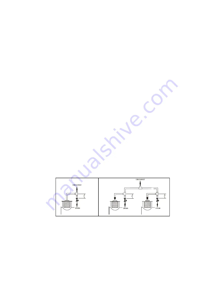
connection on top of the separator reservoir leading outside. Install a dripleg with tee on the discharge line
to prevent condensables from draining back into the separator reservoir. See the “Discharge piping
diagram” on the next page.
For pump systems operating in parallel on a common discharge, we recommend the installation of a
suitable check valve close to the separator discharge flange of each unit. When discharging more than one
pump in a common discharge line and/or over a long distance, oversize pipe accordingly.
Discharge piping diagrams
Cooling water piping (water cooled systems only)
Water-cooled systems require an adequate supply of cooling water at a maximum of 85°F and a minimum
supply pressure of 20 psig. If the cooling water temperature is higher or available pressure lower, consult
your dealer or call the factory.
The cooling water outlet connection of the heat exchanger may be fitted with an optional automatic
temperature control valve, which regulates the cooling water flow rate depending on pump operating
temperature. The valve is preset at the factory. To raise the system operating temperature, turn the valve-
adjusting screw counter-clockwise. To lower operating temperature, turn clockwise. Normal system
operating temperature is between 140° - 185° F. The valve will only open when the system operating
temperature is reached.
Dekker Vacuum Technologies, Inc. – Vmax/13
7


