


3 Description of the Equipment
5
DEKEMA Dental-Keramiköfen GmbH, AUSTROMAT
®
D4, Version 3, 2006
3 D
E S C R I P T I O N O F T H E
E
Q U I P M E N T
3.1 FRONT
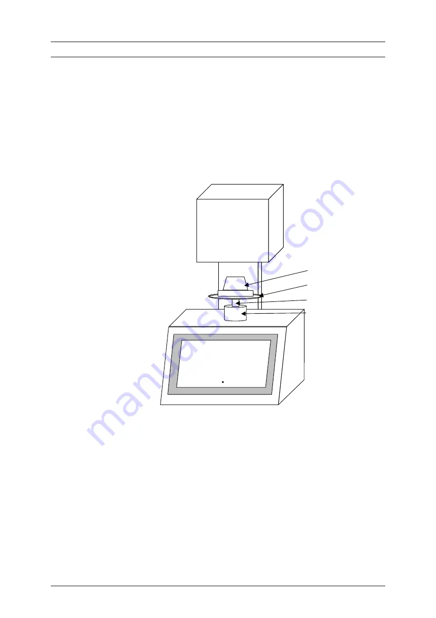
Fig. 1 and 2 are schematic illustrations of the front and rear of the
AUSTROMAT D4
.
Figure 1
Front view
AUSTROMAT D4
The top of the furnace contains the firing chamber. The bottom section of the
furnace contains the electronic and mechanical furnace components used to move
the lift system comprising the lift rod, lift seat with sealing ring (yellow O-ring), and
the firing table on which the objects to be fired are placed. On the cover plate, there
is a cylindrical height gauge that corresponds with the free height of the firing
chamber.
On the front of the bottom part of the furnace, you will find the following controls:
screen, function keys (softkeys), alphanumeric keypad, control keys, and an LED to
display when the device is ready to be used.
top section of
furnace with
firing chamber
back column
bottom section of
furnace with
electronic and
mechanical
components
LED
ON / OFF
height gauge
firing object
lift rod
lift seat with
sealing ring
firing table
Display
CREAMAT
lid
keypad
ON


