4, rue de Jarente - F 75004 Paris
Tel: +33 (0)1 71 18 18 60
Fax : +33 (0)9 70 80 10 00
S A S a u c a p i t a l d e 1 0 5 0 0 0
€
R C S P a r i s B 4 0 2 2 1 1 0 1 5
T V A : F R 0 5 4 0 2 2 1 1 0 1 5
24/29
DETAILS 3 and 4 :
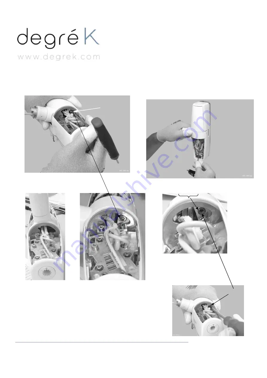
3. Réglage du frein de l’articulation rotative de la tête LOLe
3- Rotate the joint assembly so that you can reach the
locking and adjustment screws located on the joint
assembly
View before rotation after rotation, view of the locking screw access to adjustment screw when locking screw removed
4- Hold the light assembly in vertical position
(see picture bellow) and unscrew the locking screw
using a 3mm Allen key.
5- Adjust the rotational friction of the joint by
tightening the screw located on the joint
assembly using a flat-head screwdriver:
tightening the screw increases the friction
6-
Attach the back covers and handles back to their position.
Attach the light assembly to the light arm according to the
instructions given § II- 4. page 14.


