Define Instruments PRO-TC-HV Manual Download Page 14

PRO-TC-MAN-17V01 (0802)

Copyright © 2017 Define Instruments

14

_ _ _ AVERAGING SAMPLES

 scrolls across the display and toggles with the cur-

rent averaging. Using the 

 and 

 buttons, alter the number of input samples 

that the controller will average, and then press 

.

This feature allows signal averaging 
of each individual input channel, to 
optimise stable measurement. (This is 
different from Multi-Channel Averaging, 
as explained in 5.4A.)
If the change in input exceeds the averag-
ing window value it will not average, en-
suring fast response when there are large 
differences between readings.
Increasing the number of 

AVERAGING 

SAMPLES

 will stabilise measurement, but 

it will also slow down response rates.
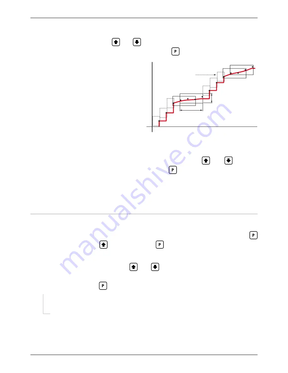
Inp

ut si

gnal in co

un

ts

Sampling

Averaging window

in displayed counts

Number

of samples

Input exceeds

averaging window

G  _ _ _ AVERAGING WINDOW

 scrolls across the display and toggles with the cur-

rently selected signal averaging window value. Using the 

 and 

 buttons, 

alter the signal averaging window. Then press 

.

If your input signal contains large noise spikes, you can increase the size of the averaging win-
dow to ensure that these are still averaged. However, increasing the window size too far will re-
duce the ability of the controller to respond quickly to real changes in input signal. Setting 

AV-

ERAGING WINDOW

 to 

0

 will give continuous averaging as per the selected averaging samples.

6.3 - Display setup

A  _ _ _ DISPLAY SETUP 

scrolls across the display and toggles with 

SKIP

. Press 


to skip to 6.4, or the 

 button and then 

 to 

ENTER

 display setup.

B  _ _ _ DISPLAY SOURCE

 scrolls across the display and toggles with the currently 

selected display source. Use the 

 and 

 buttons to choose between: 

AUTO

TEMP 1

TEMP 2

TEMP 3

TEMP 4

AVETMP

MAXTMP

, M

INTMP

PEAK

, or 


VALLEY

. Then press 

.


¨

If you selected 

AUTO

, continue to 6.3C now.


¨

If you selected something else, skip to 6.3D now.

Note that your options in this step will be limited by the 'Number of Sensors' selected in 6.2D. 
For more information about display data sources, see 5.2.
In 

Auto

 mode, the main display constantly cycles through all available input channels (I.e. 

TEMP 

1

, followed by the current value for that channel, then 

TEMP 2

TEMP 3

 etc).

Summary of Contents for PRO-TC-HV

Page 1: ...is averaged value for a display source or for setpoint activation Contents 1 Specifications 2 2 Front Panel Display 3 3 Wiring 5 4 Dimensions Installation 8 5 Data Sources 10 6 Input Setup Calibration...

Page 2: ...tput Analog output type 1 x Isolated 16 bit 4 20mA 0 10V selectable Features Fully scalable Window pro grammable over any range within the controller s full scale range Comm Port Number of serial port...

Page 3: ...1 89 your settings and advance to the next step in the setup process This button is typically used to scroll through options or increase values in the setup menu Pressing this button from the main dis...

Page 4: ...pear in the order shown in the table below and will cycle continuously at each press of the or button Press at any time to return to normal operating mode PEAK and VALLEY may be reset to zero by pres...

Page 5: ...analog input module as shown referring to the product label The unit accepts input from up to four ther mocouple sensors To use less than four sensors select your number of sensors in 6 2D TC3 TC2 TC1...

Page 6: ...S RS485 screw terminal N C SGND 5V DC option RXD TXD N C S2R D D SGND S4S 3 6 Function pins See 3 1E Connect external switches as shown to enable a function to be executed when its switch is activated...

Page 7: ...e power supply as show in the diagrams below Check the label on the unit against the colour of the connector Orange High voltage 85 265V AC 95 370V DC Black Low voltage 15 48V AC 10 72V DC High voltag...

Page 8: ...ONS INSTALLATION 4 1 Case dimensions Cabling Allowance 96mm 3 78 92mm 3 62 120mm 4 72 39mm 1 54 155mm 6 10 minimum depth required behind panel 4mm 0 16 Cabling Allowance 48mm 1 89 45mm 1 77 120mm 4 72...

Page 9: ...e meter back C Slide the Panel Gasket over the rear of the unit to the back of the Meter Faceplate D From the front of the panel insert the meter into the Panel Cutout Holding the unit in place engage...

Page 10: ...ill be displayed on the screen when the controller is in normal operating mode you can set this in 6 3B Most of the available data sources can be selected see 5 1 You can also select AUTO which will c...

Page 11: ...rmocouple input chan nels as selected in Number of Channels for Multi Channel Functions 6 3G This value can be used as the default view for the operational display or as a data source for analog outpu...

Page 12: ...the Pk Val or Hold pins in MPX mode you need to allow a settling time of at least 0 5 seconds before reading the analog output current 5 5 Peak Valley Peak and Valley are the maximum and minimum value...

Page 13: ...the display and toggles with SKIP Press to skip to 6 3 or the button and then to ENTER input setup B _ _ _ MAINS FREQUENCY scrolls across the display and toggles with the current selection Use the an...

Page 14: ...window Then press If your input signal contains large noise spikes you can increase the size of the averaging win dow to ensure that these are still averaged However increasing the window size too far...

Page 15: ...s in this step will be limited by the Number of Sensors selected in 6 2D Additionally if your display source 6 3B is set to either PEAK or VALLEY then DISP will not appear as an option as this would c...

Page 16: ...t of the calibration menu 6 5A To proceed to 6 6 you must select SKIP at 6 5A A _ _ _ CALIBRATE scrolls across the display and toggles with SKIP Press now to skip to 6 6 or use the and buttons to sele...

Page 17: ...ss the button and then to ENTER analog output setup B _ _ _ DATA SOURCE FOR ANALOG O P scrolls across the display and toggles with the current analog output data source Use the and buttons to select a...

Page 18: ...ormation on serial modes and registers A _ _ _ SERIAL SETUP scrolls across the display and toggles with SKIP If your controller does not have a serial port installed or you do not wish to configure yo...

Page 19: ...d buttons select NONE ODD or EVEN and then press F _ _ _ SERIAL ADDRESS scrolls across the display and toggles with the currently selected serial address Use the and buttons to alter the serial addres...

Page 20: ...d toggles with 0 Use the and buttons to enter your security code factory default 1 Then press If the correct PIN is entered setup is started at 7 2 If an incorrect PIN number is entered _ _ _ INCORREC...

Page 21: ...K or VALLEY and then press Note that your options in this step will be limited by the Number of Sensors selected in 6 2D See Section 5 for more information on setpoint data sources F _ _ _ SP ACTIVATI...

Page 22: ...selected setpoint Use the and to select either OFF or ON and then press When enabled this option allows the selected setpoint s value to be edited directly after press ing the button without needing...

Page 23: ...ct access menu will proceed through all access enabled setpoints in this fashion Pressing for the last ena bled setpoint will exit and return to the operational display 9 RESET PIN NUMBERS VIEW FIRMWA...

Page 24: ...aborts the operation In Custom ASCII mode data is normally read as formatted data which includes decimals and any text characters that may be selected to show units However it is also possible to read...

Page 25: ...15 Serial mode 16 Bit Unsigned Address Function 4181 4184 Hysteresis SP1 4181 SP2 4182 SP3 4183 SP4 4184 4197 4200 Make delay SP1 4197 SP2 4198 SP3 4199 SP4 4200 Note Address 16543 is a read write nul...

Page 26: ...ess Function 404181 404184 Hysteresis SP1 404181 SP2 404182 SP3 404183 SP4 404184 404197 404200 Make delay SP1 404197 SP2 404198 SP3 404199 SP4 404200 32 Bit Signed 2 x 16 Bit LSW MSW Function 400007...

Page 27: ...ger A output strings are constructed as shown Start Sign Output Value Status End Start STX character ASCII 02 Sign Output value sign space for and dash for Output Value Seven character ASCII string co...

Page 28: ...land Ph 64 9 835 1550 Fax 64 9 835 1250 sales defineinstruments co nz www defineinstruments co nz United States Dallas TX Ph 214 926 4950 sales defineinstruments com www defineinstruments com South Af...

Reviews: