

37
4
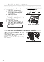
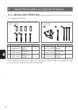
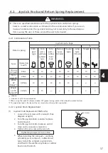
4.2. Joystick Knob and Return Spring Replacement
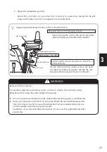
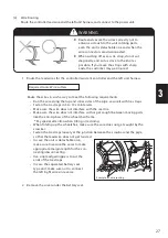
WARNING
There are specified combinations for the joystick knobs and return springs.
Select a correct combination as indicated in the combination table. If you use an
incorrect combination, the joystick knob may not return fully to the neutral posi-
tion, causing the user or those around the user to be injured.
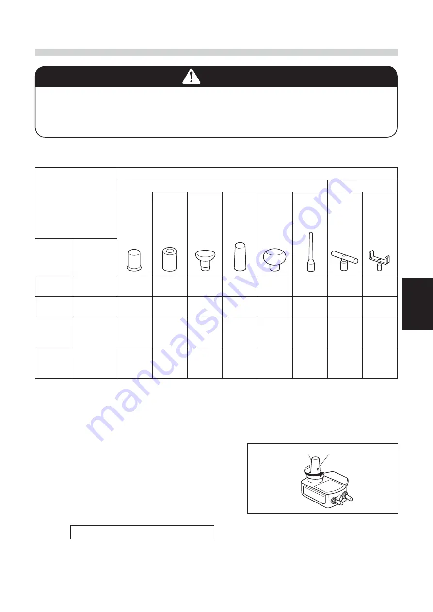
4.2.1. Combination Table
Return spring
Joystick knob shape
a
b
Com-
pact
type
Com-
pact +
urethane
cylinder
type
Com-
pact +
rubber
bowl
type
Narrow
type
(60 mm)
Round
type
Long
type
(135 mm)
T-shaped
U-shaped
Type
Operation
load*2
Strong
SP (red)
5 Nm
{
{
{
{
{
{
{
{
Stan-
dard SP
2 Nm
{
{
{
{
{
{
{
{
Weak
SP
(blue)*1
0.9 Nm
{
{
{
{
{
×
×
×
Weak-
est SP
(green)*1
0.5 Nm
{
{
×
×
×
×
×
×
{
: Usable
× : Do not use with this combination
*1 When using the weak SP (blue) or weakest SP (green) spring, contact the wheelchair manufacturer.
*2 The operation load is the load at the set screw when the joystick is operated.
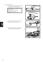
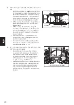
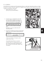
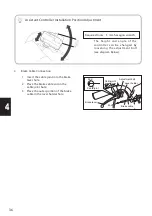
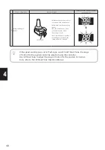
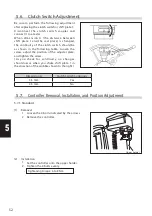
(1)
Joystick Knob Replacement Method (a)
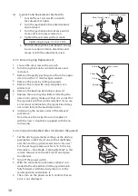
4.2.2. Joystick Knob Replacement
1 Loosen the set screw with a wrench. (See
diagram at right.)
2 Turn the joystick knob counterclockwise
and remove it.
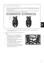
3 Turn the joystick knob clockwise until it
stops and is securely screwed on.
4 Tighten the set screw with a wrench.
Tightening torque: 0.1 to 0.3 Nm
5 When installing the c urethane
cylinder type or c rubber bowl
type, install the compact joystick knob,
and then fit the urethane cylinder or rubber
bowl onto the knob.
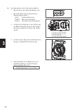
Knob
Set screw


