6.2 Optional Equipment Non-Error FIPs
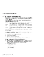
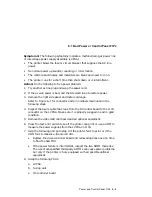
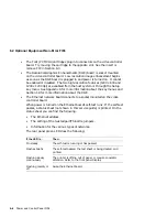
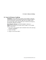
6.2 Optional Equipment Non-Error FIPs
When the Test (power up) Page builds in memory, the video control board
checks for installed options. Each option is listed as installed or not installed
on the printed sheet. The sheet also lists the amount of installed memory. See
Section 4.1 for information about the Test Page.
If any of the options that you know are installed, fail to list on the Test Page,
swap or replace the option or the connecting FRUs to diagnose and repair the
problem. The following is a list of the optional equipment:
•
The envelope feeder is powered by and communicates with the paper feeder
control board. Feed failures and paper jams are typical envelope feeder
problems.
•
The hard disk is mounted on, powered, and operated by the video controller
board. Section 6.11 lists all the hard disk error messages.
•
There are two independent SIMM sockets on the video controller board. If
only one SIMM is installed, it can mount in either socket. If two SIMMs
are installed, they can be of different sizes and installed in any order.
Memory is available, from Digital Equipment Corporation, in 4-, 16-,
or 32-Mb SIMM boards. A customer can purchase and install standard
personal computer memory. The SIMMs must comply to the following
requirements:
•
32-bit wide, non-parity, 72-pin SIMMs that conform to JEDEC
Standard 21.
•
36-bit wide, parity, 72-pin SIMMs such as the PC74M-AA/AB/AC
•
The 4-, 8-, and 16-Mb SIMMs are described as single bank, fast-page-
mode read/write memory with cas-before-Ras refresh
The Test Page lists the available RAM. 2-Mb is built in and each installed
SIMM adds to this number. For example, if you had installed a 16-Mb and
a 4-MB SIMM, you will see 22-Mb of RAM on the Test Page.
If a SIMM is bad, that entire SIMM’s memory will fail to list on the Test
Page. For example, if you installed 16-Mb and 4-Mb SIMMs and you saw
6-Mb of RAM on the Test Page, you would know that the 16-Mb SIMM is
bad or incorrectly installed.
•
The LCIT mounts under the printer. It is powered by and communicates
with the feed controller board. Most LCIT malfunctions result in feed
failures or jams.
Power and Control Panel FIPs 6–5
Summary of Contents for DEClaser 5100
Page 10: ......
Page 13: ...DSG 000172 Notes 1 ...
Page 14: ......
Page 61: ...2 5 HVPSA Figure 2 12 EP ED Cartridge DSG 000612 2 1 3 4 5 6 7 Technical Description 2 25 ...
Page 62: ...2 5 HVPSA DSG 000172 Notes 2 26 Technical Description ...
Page 70: ...3 2 Control Panel Operation DSG 000172 Notes 3 8 Operating the Control Panel ...
Page 90: ......
Page 124: ...7 5 Phantom Jams DSG 000172 Notes 7 8 FIPs for Fixing Paper Jams ...
Page 167: ...9 12 Board DC Control 1 2 4 5 7 8 9 6 3 10 DSG 000657 Removing and Replacing FRUs 9 31 ...
Page 224: ...10 1 Field Replaceable Units DSG 000172 Notes 10 4 FRU Part Numbers ...
Page 254: ...B 4 Connecting to OpenVMS VAX or ULTRIX Systems DSG 000172 Notes B 10 General Information ...
Page 264: ...D 3 Tools DSG 000172 Notes D 4 Training Documentation and Tools ...
Page 274: ......

