2.4 Scanner
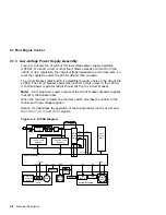
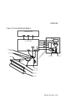
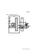
Figure 2–10 Scanning System Diagram
DSG-000610
Modulation
Laser Current
Source
Laser Driver
Video Controller Board
DC Control Board
J206-6
-2
-3
-4
-5
APCOUT
LON
ENBL
VDATA
APCIN
BD
VDO
VSYNC
BDI
SCNCLK
SCNON
SCNRDY
Scanner Motor
and Mirror
Focus Lenses
BD Mirror
Cylindrical Lens
Beam Detector
Flat Mirror
Print Drum
Laser Diode
Photo Diode
Technical Description 2–21
Summary of Contents for DEClaser 5100
Page 10: ......
Page 13: ...DSG 000172 Notes 1 ...
Page 14: ......
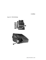
Page 61: ...2 5 HVPSA Figure 2 12 EP ED Cartridge DSG 000612 2 1 3 4 5 6 7 Technical Description 2 25 ...
Page 62: ...2 5 HVPSA DSG 000172 Notes 2 26 Technical Description ...
Page 70: ...3 2 Control Panel Operation DSG 000172 Notes 3 8 Operating the Control Panel ...
Page 90: ......
Page 124: ...7 5 Phantom Jams DSG 000172 Notes 7 8 FIPs for Fixing Paper Jams ...
Page 167: ...9 12 Board DC Control 1 2 4 5 7 8 9 6 3 10 DSG 000657 Removing and Replacing FRUs 9 31 ...
Page 224: ...10 1 Field Replaceable Units DSG 000172 Notes 10 4 FRU Part Numbers ...
Page 254: ...B 4 Connecting to OpenVMS VAX or ULTRIX Systems DSG 000172 Notes B 10 General Information ...
Page 264: ...D 3 Tools DSG 000172 Notes D 4 Training Documentation and Tools ...
Page 274: ......

