


6.
Ensure that your ICP1 is
not
yet connected to the DSPB, and ensure that its switch
is set to ‘1’.
7.
Plug a micro USB cable into the PC running SigmaStudio, and then connect the cable to your
ICP1.
a.
Note: If the connection below is not successful, it is imperative to try a different USB
cable. Many micro USB cables endure a lot of abuse from charging devices, and
although they might still provide power, they might have issues transferring data. Some
micro USB cables struggle to ever work properly with data at all.
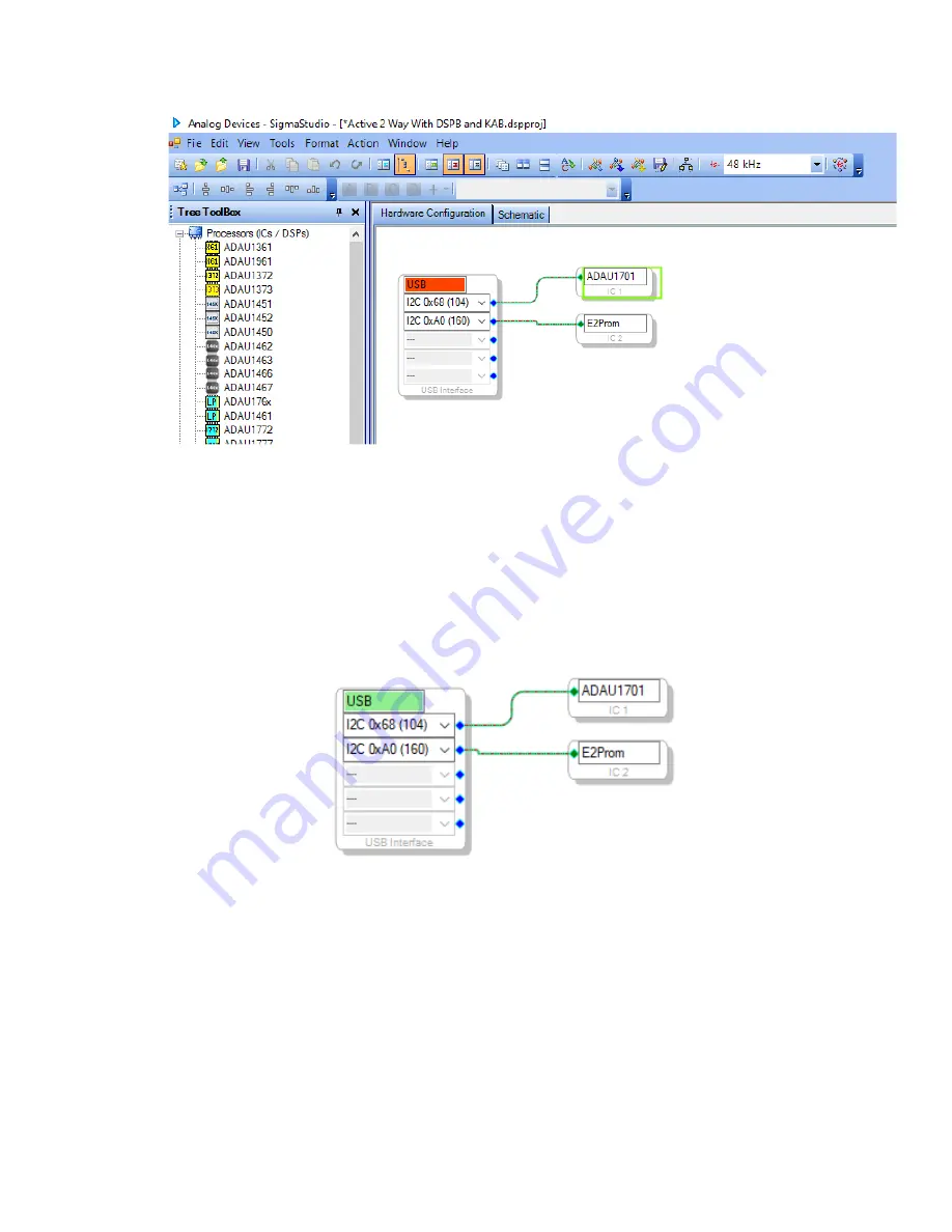
8.
If all is correct, you will see the USB block turn green, like below.
a.
Note that this means that SigmaStudio recognises your ICP1, it does not indicate that
SigmaStudio recognises your DSPB.
9.
If not already, make sure your DSPB is connected to its own power source. If the ICP1 is plugged
into the DSPB, but your DSPB does not have its own power, it will light up LEDs on the DSPB
(making it look like it is powered), but it will fail to program and function.
10.
Once the USB block is green, plug the 6-pin connector on the ICP1 to the 6-pin programming
port on the DSPB (J8 for DSPB-100 or DSPB-250, J11 for DSPB-K). Your ICP1 will come with this
cable.
11.
Following these steps, you should be ready to create custom configurations for your DSPB.
12.
If using a completely new SigmaStudio project, usage of the potentiometers on the board
requires additional configuration. If using a sample project from Dayton Audio, this should
already be configured, but is worth checking anyway.
Summary of Contents for DSPB Series
Page 37: ...4 Wiring Diagrams DSPB 100 ...
Page 38: ......
Page 39: ...DSPB 250 ...
Page 40: ......
Page 41: ...DSPB K ...
Page 42: ...DSPB KE ...
Page 43: ...DSPB ICP1 ...
Page 46: ......


