background image


3


1.1 

Important Note 

◇ 

Please read the instructions carefully before installing and operating, in order to not cause unnecessary 

damage. Do not allow any untrained non-professional workers to install or operate this machine. The 
manufacturer will not be responsible for any accidents or damages because false installment or wrong 
operation. 

◇ 

Without the approval of manufacture, any user shall not change the parts or structure of the machine 

without  permission.  If  there  is  any  damage  causes  because  of  that,  the  manufacturer  will  not  be 
responsible. 

1.2 

Qualified users 

1.2.1 

Only professionally trained personnel can operate and use the product. 

1.2.2 

Electrical hookups must be put in place by professional electrician. 

1.2.3 

non-professional nor non-trained personnel shouldn’t come close to the product working area. 

1.3 

Notes 

1.3.1 

Before  operating  this  product,  please  carefully  read  every  part  of  its  manual,  especially  Safety 

Operation and Mechanical Maintenance. 

1.3.2 This Tire Changer must be operated by professional well-training personnel. 

1.3.3 Tire Demount/Mount is forbidden to operate near or around explosive gas. 

1.3.4 Before the machine is connected to electric power and air supply, the users must check and ensure that 

the electric power and air supply fulfil the machine’s mechanical requirements. The circuit system must be 
operated by professional staff. 

1.3.5 During operation, do not face the Clamp Wheel, in order to avoid dust or other debris in the operator's 

eyes.  During  mechanical  operation,  do  not  touch  the  inflatable  pedal,  in  order  to  avoid  accidents.  Wear 
proper protective equipment 

1.3.6    While  inflating tires  you  must be very  careful, strictly  following instructions  for inflation.  If tires 

suddenly burst, tire assembly machine design and structure is not to protect the operator's personal safety It 
is the Technicians job to use  proper safety equipment .  

1.3.7 Do not wear any loose items during machine operation , necklaces, loose clothing, etc., may bring the 

operators personal injury. 

1.3.8 During tire demount/mounting, the Clamp Wheel should always rotate clockwise; Counter clockwise 

rotation indicates machine fault or operator error. If it is operation error please do it in right way. If there is 
machine fault, please stop the electric power and send the machine to repair. 

1.3.9  The  manufacturers  will  not  be  responsible  for  the  damage  or  injury  if  users  use  parts  from  other 

factories. 

1.3.10 Regularly inspect the level of oil . If the oil level is low,  unscrew the cover and add oil.  

1.3.12 If the product is not used for a long time, please disconnect all power supply and lubricate the Clamp 

Wheel and Center Spindle to prevent oxidation. 

1.3.13 When deciding to scrap equipment, please do ensure all power supply has been cut off. Follow 
native and national laws and regulations about all non-ferrous metals and non-ferrous metal scrap or 
return to budget automotive equipment.  

Summary of Contents for C896CMLL

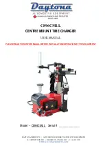
Page 1: ...E EQUIPMENT 101 APPLEWOOD DR BRIGHTON ON K0K 1H0 1 866 219 9991 WWW DAYTONAPRODUCTS COM C896CMLL CENTRE MOUNT TIRE CHANGER USER MANUAL PLEASE READ THIS ENTIRE MAUAL BEFORE INSTALLATION OPERATION OF THIS EQUIPMENT Model C896CMLL Serial _____________ ...

Page 2: ... to ensure that the product has not been damaged The manual is an important part of product Please put it in the place where you can find it at any time In the installation process if signs of damage or defect appear please contact the manufacturer in time to replace the defect ...

Page 3: ...e 6 Installation and commissioning instructions 7 3 1 Pre Installation Preparation 7 3 2 Precautions during installation 8 3 3 installation 8 3 4 Check the project table after installation 9 3 5 Commissioning and debugging 10 Operation declaration 12 4 1 Operating notes 12 4 2 Demount and Mount Tires Operation Procedure 13 Maintenance storage and scrap 16 5 1 Maintenance 16 5 2 Storage and scrap 1...

Page 4: ...rofessional staff 1 3 5 During operation do not face the Clamp Wheel in order to avoid dust or other debris in the operator s eyes During mechanical operation do not touch the inflatable pedal in order to avoid accidents Wear proper protective equipment 1 3 6 While inflating tires you must be very careful strictly following instructions for inflation If tires suddenly burst tire assembly machine d...

Page 5: ...er should be less than 70dB The machine can be fixed in the ground by screws to reduce noise 1 6 Training Only professional workers with good training can operate this machine The manufacturer can provide training if the users need it 1 4 Danger warning signs ...

Page 6: ...orks especially well for Run flat and low profile tires It is made to protect high standard tires 2 2 Technical Specifications Rim of tires 10 28 Max Tire Diameter 46 8 Max Tire Width 16 7 Hydraulic Wheel Pressure 3000kg Working Pressure 8bar 10bar 116 145psi Max Inflation pressure 3 5bar 50psi Working Voltage 220V 1ph 380V 3ph 110V1ph Motor Power 1 1kw 0 75kw 1 5kw Outline dimension 1380 900 1500...

Page 7: ...ydraulic pump and Solenoid Valve Z Hook Control Valve K Wheel Control M Hook Back forward Valve S Electric Cabinet P Scram Button V Pedal Switch G Oil Drier Y Turntable N Hook C Inflation Gun E Automatic Hydraulic Wheel F Hook up down Valve M K P G Y R S N U Picture3 Z F I C V G ...

Page 8: ...ystem Equipment installation location should be at least up to the standard shown in Picture 4 and 4 A which can ensure the normal operation and that the machine parts are not subject to any restrictions The tire changer is forbidden to use in explosive gas Picture 4 Picture 4 A 3 1 3 Inspection Products After receiving the product please inspect the machine package transportation and wet damage p...

Page 9: ...r lost parts If any error is found please contact us immediately If the users find error but still operate the equippment the manufacturer will not assume any responsibility If there is any questions please do not use the machine but contact the supplier 3 2 Installation and assembly For installation or assembly please contact us or a qualified trained professional If assembling your self and you ...

Page 10: ... the connection with the power supply please do make sure the user s power supply and air supply meet the requirements of the machine The machine is connected to the circuit The circuit must be standard equipped with a fuse ground wire and the automatic circuit breaker of 25A according the operation rule Note Only the professional personnel can do the circuit work The power plug of the tire change...

Page 11: ...ovement to make the Hook forward and backward as Picture7 E 7 F Hook Wheel Z as Picture7 C 7 D and Hook Disk K as Picture 7 G 7 H 3 5 3 Hook head adjustment The position and angle of Hook Head has been adjusted standard by the manufacturer in factory The users should not change it Upper of the Hook Head there is Hand Wheel which can be pulled upside For the first time to use this machine the users...

Page 12: ...11 Picture8 Picture8 A Picture8 B Picture8 C Picture7 E Picture7 F Picture7 G Picture7 G Picture7 A Picture7 C Picture7 D Picture7 B ...

Page 13: ...t Tires Operation Procedure 4 2 1 Check whether the air inside of tires has been totally driven out If not please drive air out completely As shown in Picture 9 and Picture 9 A press tire with the wheel Disk and step the Motor Pedal to smear the lubricating oil Picture 9 Picture 9 A 4 2 2 Demount tires After bead breaking the rim edge should be coated with special lubricant Fix tires in Center Spi...

Page 14: ...ressure monitoring device when demount tires with tire pressure monitoring device Generally when Center Spindle turns a half circle the up bead can leave the wheel Practice more it will never scratch or do other damage to wheels rims or tires As shown in Picture 12 D pull the controller make the Hook side down As shown in Picture 12 D move the Hook Head Z against bottom rim about 3mm 5mm Turn up t...

Page 15: ...wnside coat the lubricant up and down of rims as shown in Picture 13 A and coat the lubricant to tires as shown in Picture 13 B Put the tire on the wheel as shown in Picture 13 B The Straight Head should be about 4 5mm to the rim and its Straight Head touches the tires as shown in Picture 13 B Notice ...

Page 16: ... Helper Arm down to the rims 10 12mm as shown Picture 13 F Notice For run flat tires please do always according to the actual condition adjust the position of the Work Heading and the movement of hydraulic equipment If the Working Head is not adjusted in right position which stepping the Pedal it will tear tires Generally when the Center Spindle turns a circle tire can be mounted Then turn back th...

Page 17: ...sure until the pressure reaches the specified value of the tire Note use the inflated gun to inflate the tire regularly check the pressure of the inflation gauge Picture 14 Maintenance storage and scrap 5 1 Maintenance 5 1 1 Maintenance Prohibit unauthorized personnel for maintenance operation To extend the service life of the tire changer maintenance should be performed according to the requireme...

Page 18: ...rail with lubricant oil As shown in Picture 15 A control oil mist level in the Oil Drier If the oil level is lower you need to unscrew the Oil Drier cover F and then as figure 15 A add some oil When stepping the pedal 3 to 4 times check whether there is oil drops into the oil cup F if not adjust screw D As shown in Picture 15 C machine motor is not powerful enough adjust the triangle belt of the m...

Page 19: ...le at the fastest speed Problems Causes Resolutions Unidirectional rotation of the Center Spindle Universal steering switch damage Replace universal steering switch Center Spindle does not rotate Triangle damage Replace triangle belt Universal steering switch damage Replace universal steering switch Motor damage or wire damage Check motor and external plug or socket The Clamp Wheel cannot work Dus...

Page 20: ...7 0 Explosive View ...

Page 21: ...r for Column moving 6 006 Hook and Controller 7 007 Double Wheel Disk for up and down 8 008 Crossing Switch 9 009 Fixing Plate for Column 10 010 Electricity Control Box 11 011 Pedals 12 012 Oil Drier 13 013 Box 14 014 Pump 15 015 Pump and Lift Connector 16 016 Central Spindle and Gear Box 17 017 Lift Frame 18 018 Motor 19 019 Body Weldment24 ...

Reviews:

Related manuals for C896CMLL