background image


4096-225 


3.4M & 3.7M Az/El TRUSS MOUNT 


21 

 
4.1 

FEED HORN ASSEMBLY 

 
Ku-BAND FEED 
 

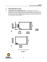
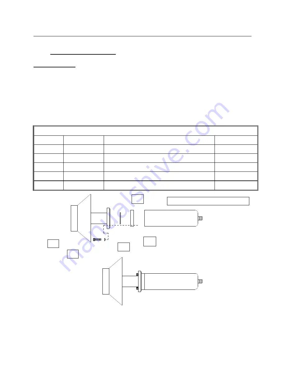
SINGLE  POL  -  Coat  the  o-ring  (item  #2)  with  the  silicone  grease  from  the  capsule 
provided and place it in the feed horn o-ring groove. Place the square adapter (item #3) 
on the feed horn flange and line up the four hole pattern in the adapter with four of the 
eight  holes  in  the  feed  horn  flange.  (Note  that  the  adapter  will  only  line  up  one  way.) 
Place the LNB (customer provided) on the adapter so that the holes in the LNB line up 
with the feed/adapter holes and secure with four screws (item #4). See figure 1. Tighten 
securely. 
 

Ku-BAND - SINGLE POL - PARTS LIST 

ITEM # 

PART # 

DESCRIPTION 

  QUANTITY 

0183-277 

FEED HORN ASSEMBLY 

0198-120 

O-RING 

0202-067 

TRANSITION ADAPTER 

8300-017 

#6-32 x 7/8" SS STD 

8200-010 

#6 LOCKWASHER 

[ 1 ]


[ 4 ]


[ 5 ]


[ 2 ]


[ 3 ]


CUSTOMER PROVIDED LNB


FIGURE 1.


DAWNco • 3340 S. Lapeer Rd • Orion, MI 48359-1320 • Ph (248) 391-9200 • Fax (248) 391-9207 • [email protected]

Summary of Contents for P37F

Page 1: ...dhorn LNB and pipe sold separately Click here for DAWNco Phone 248 391 9200 sales DAWNco com P37F Install Manual DAWNco 3340 S Lapeer Rd Orion MI 48359 1320 Ph 248 391 9200 Fax 248 391 9207 sales DAWN...

Page 2: ...oved 3 0M antenna 9 11 97 PGW F Pol was pole 7 11 97 PGW E Revised Hdw Qty On Pg 28 Per Ecn 1709 And Added Revision Page 08 04 94 RF ORIGINAL RELEASE 11 03 92 R FRYE REV DESCRIPTION DATE APPROVED 4096...

Page 3: ...List 2 2 Reflector Pre Assembly 2 3 Reflector Assembly 2 4 Brace Mount Brackets 2 5 Support Structure Assembly 3 0 Reflector Installation 3 1 Reflector Mount Part List 3 2 Canister Elevation Rod Assem...

Page 4: ...has been received and is in good condition A complete packing list for each major component is supplied 2 FREIGHT DAMAGE Any damage to materials while in transit should be immediately directed to the...

Page 5: ...der to achieve maximum performance of your antenna system it is important to select the correct location for the antenna The following guidelines should be observed when selecting a site for the insta...

Page 6: ...inimum compressive strength of 3000 PSI at 28 days Per ACI 318 77 3 Soil bearing capacity should be no less than 2000 PSF 4 Concrete should be poured against undisturbed soil 5 Allow concrete 24 hours...

Page 7: ...0179 141 0179 260 REFLECTOR PETAL W O HOLE REFLECTOR PETAL W O HOLE 4 4 3 0217 072 0217 073 FEED SUPPORT CLEVIS FEED SUPPORT CLEVIS 4 4 4 0490 301 CENTER HUB 1 1 5 0156 808 CENTER PLATE 1 1 6 0211 404...

Page 8: ...f the reflector should be on as level a surface as possible to prevent warping or misalignment of the reflector s parabolic shape during assembly Any loss of contour may affect the antenna s signal qu...

Page 9: ...A Identify the reflector petals and parts of the reflector support structure according to the parts list We recommend that you hi lite the column for your specific antenna B Note that four of the peta...

Page 10: ...petals rim down on a level surface with their flanges next to each other A wooden support 23 25 long for the 3 4M and 24 for the 3 7M such as a 4x4 will help support the narrow ends of the petals Wood...

Page 11: ...4096 225 3 4M 3 7M Az El TRUSS MOUNT 11 2 4 BRACE MOUNT BRACKETS FOR 3 4M AND 3 7M 3 7M 12 13 14 4 6 5 Wood Support Petal...

Page 12: ...he reflector center Use the existing 3 8 hardware Do not tighten this hardware until instructed Attach the reflector support brackets item 6 to the reflector at locations B and C at the left side of a...

Page 13: ...g support brace item 7 to the underside of the upper ring with 3 8 hardware items 15 16 17 18 Do not tighten Upper Ring Center Hub 16 17 18 15 16 7 A Position the remaining end of the long support bra...

Page 14: ...enter in the center hub by tightening the 1 4 bolts to the center plate Next tighten all the hardware that attaches the support brackets to the reflector Tighten the outermost bolts securing the long...

Page 15: ...TION ADJUSTMENT BLOCK 1 3 0490 100 ELEVATION STRUT INNER 1 4 0490 306 ELEVATION STRUT OUTER 1 5 8403 008 1 2 13 x 4 00 U BOLT 2 6 8317 106 5 8 x 1 50 SQ HD BOLT 6 7 8033 012 2 8 8033 018 1 8201 030 8...

Page 16: ...NO DESCRIPTION QTY 11 8104 007 5 12 8034 016 1 13 8201 039 2 14 8202 044 1 15 8105 007 7 1 2 13 HEX NUT 5 8 11 HEX NUT 5 8 LOCKWASHER 5 8 FLATWASHER NARROW 5 8 11 x 2 00 BOLT DAWNco 3340 S Lapeer Rd...

Page 17: ...cures it with the u bolts 3 2 CANISTER ELEVATION ASSEMBLY STEP 1 STEP 2 3 4 10HEX NUT 3 4 WASHER Run a 1 2 hex nut item 11 onto each square head bolt item 6 Then insert them into the canister only a f...

Page 18: ...rut 8 9 9 10 11 Struts 3 4 Secure the struts with 1 2 hardware items 8 9 10 11 A Run one 3 4 nut item 16 up the threads of the inner strut and follow with one 3 4 washer item 17 B Insert the strut thr...

Page 19: ...vation tab on the canister is pointing towards the mast Use the reflector carton or similar object as a rest for under the edge of the reflector Orient the reflector so that the cross tube of the cent...

Page 20: ...rsons can steady the reflector in the cradle Now the other installer can secure the reflector to the canister with the U bolts and 1 2 hardware items 5 9 10 11 Tighten hardware to allow reflector to r...

Page 21: ...Note that the adapter will only line up one way Place the LNB customer provided on the adapter so that the holes in the LNB line up with the feed adapter holes and secure with four screws item 4 See...

Page 22: ...rovided to the OMT with the o rings and hardware provided with the LNB s See figure 2 Tighten securely Ku BAND DUAL POL PARTS LIST ITEM PART DESCRIPTION QUANTITY 1 0183 272 OMT Ku BAND DUAL RECEIVE 1...

Page 23: ...m 7 and gasket item 2 to the bottom of the feed horn as shown Tighten securely C BAND PARTS LIST ITEM PART DESCRIPTION QUANTITY 1 0183 294 FEED HORN ASSEMBLY 1 2 0171 073 GASKET 1 3 8023 008 1 4 20 x...

Page 24: ...ardware provided Figure 4 Tighten securely C Ku BAND FEED PARTS LIST ITEM PART DESCRIPTION QUANTITY 1 0211 405 BRACKET FEED SUPPORT 4 2 8030 006 1 4 20 x 75 BOLT 4 3 8202 040 1 4 LOCKWASHER 4 4 8100 0...

Page 25: ...T 8 Ku BAND SINGLE POL ONLY 8 0156 819 FEED COVER TAB 4 9 0250 276 FEED COVER 1 10 8320 001 8 x 1 2 TAPPING SCREW 4 11 4075 003 FEED COVER CAP 1 4 3 FEED SUPPORT ASSEMBLY STEP 1 Attach each of the fee...

Page 26: ...e feed horn to the reflector cover plate as shown in figure 8 If the focal length is incorrect adjust the feed clevises in or out at the reflector surface as needed Be sure that the clevises are adjus...

Page 27: ...6 225 3 4M 3 7M Az El TRUSS MOUNT 27 4 5 6 4 3 2 1 C Ku BAND FIGURE 7 Face of Feed Horn FOCAL LENGTH FIGURE 8 DAWNco 3340 S Lapeer Rd Orion MI 48359 1320 Ph 248 391 9200 Fax 248 391 9207 sales DAWNco...

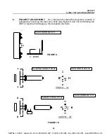
Page 28: ...ed horn bolts see figures 9 and 10 and rotating the OMT or feed horn 90 degrees then retighten the bolts FEED HORN BOLTS C BAND FIGURE 9 A A VIEW A A VIEW B B B B Ku BAND SINGLE POLE Ku BAND DUAL POLE...

Page 29: ...the feed installation connection of the cable and polarity adjustment bend the feed cover tabs item 7 in and then slide the feed cover item 8 over the tabs Attach the cover to the tabs with the tappin...

Page 30: ...htly Rotate in azimuth slowly until loss of signal is observed Rotate the antenna in the opposite direction until the signal strengthens and then weakens again Set the azimuth between these two points...

Page 31: ...ither high or low Loosen the four bolts on the long and short angle brace behind the radial line of the reflector Gently push or pull on the reflector rim until it is brought into position While one i...

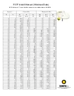
Page 32: ...63 3920 3920 30 180 2371 0 791 0 4914 0 45 0 3520 0 3802 0 2124 0 45 30 3749 181 4063 1511 2617 1511 45 60 3147 156 3056 459 265 459 45 90 99 619 99 4470 0 4470 45 120 467 652 91 4310 2488 4310 45 150...

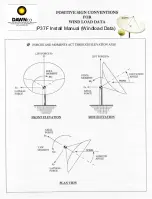
Page 33: ...P37F Install Manual Windload Data...

Reviews: