background image

5. Click “Calibrate“ in order to calibrate the camera.

In this step the software computes the position and orientation of the camera, as well as the focal 
length and distortion parameters of its lens.

6. From this moment on, do not move or adjust anything at the scanner – otherwise you will have to 

repeat the calibration.

3. Menu


  “

   Structured


    Light


    Scanning


 “: Calibration of the projector


1. When you open the Structured Light Scanning menu, the projector will again show the setup 

pattern, and both projector and camera will be set back to the settings you have made in step 1.

2. Select a profile (recommended: “default“).

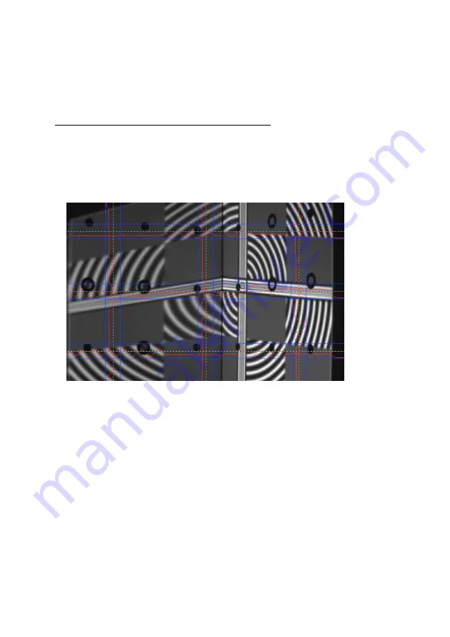
3. Check the camera image again. In those areas that show the circular wave pattern, the red intensity 

curves must not be cut off at the blue borders. Carefully adjust the lens aperture if necessary, but be 
sure not to change the focus.

4. Click “Calibrate” in order to calibrate the projector.

In this step the software measures the position and orientation of the projector, its focal length and 
distortion coefficients, as well as optical transmission properties and delays of the whole system.

Your scanner is now calibrated. This refers to the position and orientation of camera and projector relative to 
each other, and the focus and brightness settings. You may move, rotate and tilt the scanner as a whole, and 
you can close and restart the DAVID software, without losing the calibration. 

However, if you rotate camera or projector with respect to each other or change the focus (e.g. in order to 
scan much smaller or larger objects), you will have to repeat the whole calibration procedure.

10

3DPE.ir

Summary of Contents for SLS-1

Page 1: ... GmbH DAVID Vision Systems GmbH DAVID Vision Systems GmbH DAVID Vision Systems GmbH Rudolf Diesel Str 2a D 56070 Koblenz Germany Phone 49 0 261 983 497 70 Fax 49 0 261 983 497 77 Mail service david vision systems de Web www david laserscanner com 2012 2012 2012 2012 DAVID Vision Systems GmbH 3 D P E i r ...

Page 2: ...mm precision 0 1 of object size down to 0 1mm scanning time 2 4 seconds per scan mesh density up to 350 000 vertices per scan colour texturing export formats obj stl ply Requirements Standard PC Windows XP Vista or 7 32 or 64 bit Two available USB ports available VGA or HDMI port Recommended 2 GHz CPU 4 GB RAM 3d graphics card e g NVIDIA GeForce or ATI Radeon Specifications 3DPE ir 3 D P E i r ...

Page 3: ...al Adapter set for global power supply USB cable for camera Cable straps System Requirements System Requirements System Requirements System Requirements Windows XP Vista or 7 32 bit or 64 bit 3D graphics adapter Available VGA or HDMI port Two available USB ports Recommended Dual core processor 2 GHz 4 GB RAM NVIDIA or AMD graphics adapter Safety Instructions Safety Instructions Safety Instructions...

Page 4: ... scan Achievable scan Achievable scan resolution approx resolution approx resolution approx resolution approx 0 2 of object size 0 2 of object size 0 2 of object size 0 2 of object size 30 mm 30 mm 30 mm 30 mm 30 mm ca 30 mm ca 90 mm 0 1 mm 50 mm 50 mm 50 mm 50 mm 60 mm ca 40 mm ca 120 mm ca 0 1 mm 70 mm 70 mm 70 mm 70 mm 60 mm ca 65 mm ca 180 mm ca 0 15 mm 90 mm 90 mm 90 mm 90 mm 120 mm ca 80 mm ...

Page 5: ...river may require administrator rights 3 Follow the instructions on screen Projector Settings Projector Settings Projector Settings Projector Settings The projector is shipped with optimal settings We recommend not to change anything in the projector s on screen menu You can restore the recommended settings in the projector s on screen menu any time 1 Select Reset 2 Be sure to switch Auto Keystone...

Page 6: ...play This setting is required so that DAVID can project its scan patterns and show the user interface on your computer screen at the same time You can find more detailed instructions in our online user manual at http www david laserscanner com Manual in chapter 3D Structured Light Scanning When these settings are correct your monitor and projector will show different contents but with the same des...

Page 7: ...on of the Scanner Calibration of the Scanner Calibration of the Scanner Calibration of the Scanner One advantage of the SLS 1 s modular setup is that its size can be adjusted to very different object sizes Therefore calibration measurement of the current hardware setup in the DAVID software is required allowing the software to obtain undistorted 3D data at the correct scale We use a calibration co...

Page 8: ...s Only reduce it if a clean undistorted sine wave cannot be obtained otherwise 9 Look at the projected grey planes in the camera image Adjust camera focus mechanic focus ring so that the object is depicted as sharp as possible Also you can use the projected black and white stripes for focussing 10 Fasten all screws projector ball joint of camera so that nothing can be dislocated from now on 2 Menu...

Page 9: ... above the red mounting rack 3 Enter the scale size of the calibration pattern at Calibr Scale You can find the number printed on the panels right next to the respective pattern 4 The projector now shows a plane white or grey face You can adjust its brightness wit the Projector Brightness control so that the calibration markers are clearly visible in the camera image If there is enough environment...

Page 10: ...ensity curves must not be cut off at the blue borders Carefully adjust the lens aperture if necessary but be sure not to change the focus 4 Click Calibrate in order to calibrate the projector In this step the software measures the position and orientation of the projector its focal length and distortion coefficients as well as optical transmission properties and delays of the whole system Your sca...

Page 11: ...t the distance not the focus rings Important For each scan observe that the red sine waves are not cut off overdriven this refers only to the image regions where the circular wave pattern is visible Should a correction be required carefully adjust the camera aperture but do not change the focus Each click on Start performs a new scan DAVID projects a set of different stripe patterns and records th...

Page 12: ...ou can first collect more scans in the Structured Light menu and align them all later Menu Texturing You can record a texture with each scan It is coloured if you are using a colour camera otherwise it is greyscale The texture usually requires different illumination settings When the Texturing menu is open you can adjust Projector Brightness camera Exposure or other camera properties as you like w...

Page 13: ...r scan with the Selection Tool At this time you should only remove surface areas which are not useful for alignment i e which no pair of scans have in common Hint With the Arrange buttons you can arrange all scans next to each other in order to get a good overview DAVID offers several alignment modes In general you should start with the Free mode which aligns one scan to one other with each step I...

Page 14: ...ay scan 5 would be aligned to all scans which includes more overlapping areas and thus can lead to a more precise alignment Right click on the group s name in the list and choose Uncombine to separate the group again If automatic alignment cannot solve an alignment task correctly you can align scans manually by mouse keeping the Ctrl key pressed Please refer to the online manual for details 2 Scan...

Page 15: ...imbursement of the purchase price After the warranty period has expired you still have the option of sending the defective device to your supplier or to the DAVID Laserscanner after sales service for repair Repairs made after expiry of warranty will be subject to a charge Your statutory rights are not affected through this warranty Damage caused through improper handling use storage changes to the...

Reviews: