background image


18

Set Date & Time Menu 

To set the Date & Time on the HDR unit. 
 
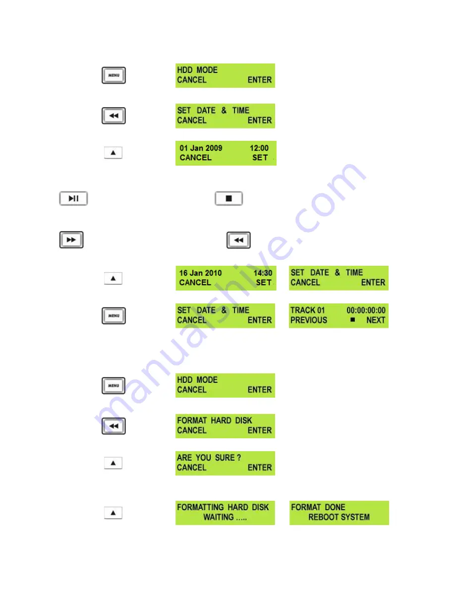
Press the Menu Button, to enter menu mode.  


Press the REW (

◄◄

) Button to navigate the menus until SET DATE & TIME is displayed. 


Press the Next (

) Button (right) to enter the SET Date & Time menu. 


You will see a flashing cursor on the date value. To set the dates use the Play/Pause Button to increase the 
value or the Stop Button to decrease the value. 


Increases Value 


Decreases Value 

Use the FWD (

►►

) Button to move the cursor to the next column to the right i.e. Month / Year / Hours / 

Minutes or the REW (

◄◄

) Button to move the cursor back to the left. 


Moves the cursor to the right. 


Moves the cursor to the left. 

Once you have set the date & time press the Next (

) Button (right) to exit the menu. 


Then press the Menu Button to leave menu mode. 


Format Hard Disk Menu 

Caution: Format Hard Disk will remove all recordings and files from the hard drive. 


Press the Menu Button, to enter menu mode. 


Press the REW (

◄◄

) Button to navigate the menus until FORMAT HARD DISK is displayed. 


Press the Next (

) Button (right) to enter the FORMAT HARD DISK menu. 


You will see ARE YOU SURE? Displayed.  
Press the Next (

) Button (right) again to confirm that you want to format the hard disk. 


After a few seconds the HDR UNIT will reboot and the display will return to normal. 

USO 

RESTRITO

Summary of Contents for HDR-40

Page 1: ...HD HDD Recorder HDR 40 HDR 50 Combined Instruction Manual Rev 180110 www datavideo tek com USO RESTRITO ...

Page 2: ...2 BIT RATE Menu 14 SD MPEG2 BIT RATE Menu 15 SET1080i H RES Menu 16 GPI Mode Menu 17 Select GPI Function Menu 17 Set Date Time Menu 18 Format Hard Disk Menu 18 Erase Track Menu 19 HDD Surface Scan Menu 19 Recording a Track SD or HD 20 Playing an M2T Track 21 Auto Rewind and Playback function 21 Connecting to a PC 22 Connecting to a MAC 24 HDR 40 HDR 50 RS 422 Protocol Reference V1 0 25 1 Interface...

Page 3: ...eed the extension cord s rating 10 Make sure that the total amperes of all the units that are plugged into a single wall outlet do not exceed 15 amperes 11 Never push objects of any kind into this unit through the cabinet ventilation slots as they may touch dangerous voltage points or short out parts that could result in risk of fire or electric shock Never spill liquid of any kind onto or into th...

Page 4: ...e one year extension to the standard Warranty providing the product is registered with Datavideo within 30 days of purchase For information on how to register please visit www datavideo tek com or contact your local Datavideo office or authorized Distributors Certain parts with limited lifetime expectancy such as LCD Panels DVD Drives Hard Drives are only covered for the first 10 000 hours or 1 ye...

Page 5: ... Standard and High Definition video equipment via SDI or HD SDI with convenient SDI loop through pass through for record monitoring Playback of recorded tracks is via HDMI output Device control is also possible via RS 422 RS 232 or a simple GPI trigger Both units provide a choice of SD or HD MPEG II M2T recording bit rates which work with a wide range of HD Non Linear Editing NLE and play out solu...

Page 6: ...or record pause record actions File Transfer to Computer From HDR unit in HDD mode via Firewire 400 IEEE 1394 connection From removable HDD enclosure via USB 2 0 connection Note These units cannot be operated as AVC Devices The AVC Command set is not supported The HDD enclosure may be supplied empty or with a drive already fitted please check with your supplier dealer These units cannot record a c...

Page 7: ...eo Office 1 Carefully remove the two screws from the 2 5 removable caddy end then pull out the PCB 2 Push the 2 5 hard drive into the socket side of the PCB turn the PCB over and use 4 supplied screws to secure 3 Slide PCB and hard drive module into removable caddy the right way up using the guide slots The USB and SATA connections should be visible at the rear of the caddy 4 Carefully replace the...

Page 8: ...ecord mode To start recording press the Record Button and Play Button simultaneously N B Unit will not record if no video signal is present Play Pause Button Starts playback of a track or pauses playback of a track status will be displayed on the Display Panel Also Starts Pauses a recording when unit is in Record mode Stop Button Stops playback or record Previous Next Buttons These buttons navigat...

Page 9: ...For CH1 L and CH2 R audio input HDMI Out Port Port for connecting to external HDMI monitors and devices HD SD SDI input and Loop through output connectors DC In Socket Connect the supplied 12V 3A PSU to this socket The connection can be secured by screwing the outer fastening ring of the DC In plug to the socket Power On Off Switch Switches the power On Off Grounding Terminal When connecting this ...

Page 10: ...p and down between recorded tracks and menu options Record Button Puts the HDR 50 into record mode To start recording press the Record Button and Play Button simultaneously N B Unit will not record if no video signal is present Play Pause Button Starts playback of a track or pauses playback of a track status will be displayed on the Display Panel Also Starts Pauses a recording when unit is in Reco...

Page 11: ... For CH1 L and CH2 R audio input HDMI Out Port Port for connecting to external HDMI monitors and devices HD SD SDI input and Loop through output connectors DC In Socket Connect the supplied 12V 3A PSU to this socket The connection can be secured by screwing the outer fastening ring of the DC In plug to the socket Power On Off Switch Switches the power On Off Grounding Terminal When connecting this...

Page 12: ...nated The 18 Menus are HDD MODE This mode allows the HDR unit to connect to a computer for drag and drop file transfers via IEEE 1394 cabling to a PC or MAC See HDD Mode Menu Page 13 for more details SETUP LOOP PLAY If set the HDR unit will continuously loop play the selected track until stopped FREE SPACE Displays how much free space is available on the current HDR unit removable drive TOTAL SPAC...

Page 13: ...te Time Menu Page 18 for more details FORMAT HARD DISK Formats the HDD and erases all files and tracks from the HDR unit See Format Hard Disk Menu Page 18 for more details ERASE TRACK Erases the selected track from the HDR unit See Erase Track Menu Page 19 for more details HDD SURFACE SCAN Checks the HDD for errors bad sectors This is only necessary if your HDR unit is not performing correctly or ...

Page 14: ...kely to be smaller than 2GB The Open GOP structure of the 1080 stream requires information contained within all these files to have a truly contiguous video audio file Some Non Linear Edit systems do not combine these m2t files when importing clips so this may need to be done prior to import Datavideo can provide a utility M2T_FileCombine exe to help you combine these multiple m2t files How to use...

Page 15: ...right Then press the Menu Button to leave menu mode HD MPEG2 BIT RATE Menu The HDR unit has user selectable encoding bit rates of 20 25 30 35 40 45 50 55 60 Mbps for recording HD tracks or M2T files To select the HD MPEG2 BIT RATE Press the Menu Button to enter the menu mode Press the FWD Button to navigate the menus until SET MPEG2 BIT RATE is displayed Press the Next Button right to enter the SE...

Page 16: ...Mode Maximum Recordable Time 120GB 20 Mbps 675 mins or 11hrs 15mins 120GB 40 Mbps 330 mins or 5hrs 30mins 120GB 60 Mbps 225 mins or 3hrs 45mins SD MPEG2 BIT RATE Menu The HDR unit has user selectable encoding bit rates of 5 10 and 15 Mbps for recording SD tracks or M2T files To select the SD MPEG2 BIT RATE Press the Menu Button to enter the menu mode Press the FWD Button to navigate the menus unti...

Page 17: ...s or 15hrs SET 1080i H RES Menu Press the Menu Button to enter the menu mode Press the FWD Button to navigate the menus until SET 1080i H RES is displayed Press the Next Button right to enter the SET 1080i H RES menu Press the FWD Button to select either 1440 or 1920 To confirm your selection and exit the menu press the Next Button right Then press the Menu Button to leave menu mode 1080i is the s...

Page 18: ...to select either Pulse Trigger or Level Trigger To confirm your selection and exit the menu press the Next Button right Then press the Menu Button to leave menu mode Select GPI Function Menu Press the Menu Button to enter the menu mode Press the FWD Button to navigate the menus until SET GPI FUNCTION is displayed Press the Next Button right to enter the SET GPI FUNCTION menu Press the FWD Button t...

Page 19: ...REW Button to move the cursor back to the left Moves the cursor to the right Moves the cursor to the left Once you have set the date time press the Next Button right to exit the menu Then press the Menu Button to leave menu mode Format Hard Disk Menu Caution Format Hard Disk will remove all recordings and files from the hard drive Press the Menu Button to enter menu mode Press the REW Button to na...

Page 20: ... disc surface for errors and bad sectors It is not generally necessary to use Surface Scan unless your HDR unit is not performing correctly or you have changed the HDD This process can take a long time depending on drive size To run the Surface Scan press the Menu Button to enter menu mode Press the REW Button to navigate the menus until SCAN HDD SURFACE is displayed Press the Next Button right tw...

Page 21: ... unit is empty The counter next to the track number on the LCD display should be showing 00 00 00 00 There is some available space on the HDR unit Hard Disk Go to the FREE SPACE Menu and check that the HDR unit is not full Check that the SDI cabling from the video source is connected correctly and is not too long or damaged Check that the source equipment is operating and set up correctly Record P...

Page 22: ... and then press the FWD Button to select ENABLE Press the Next Button right to select SET and then press the Menu Button to return to track display When you press play the selected track will start playing and will loop until the Stop Button is pressed To cancel loop playback follow the above procedure but select DISABLE instead of enable Auto Rewind and Playback function If you want to see the la...

Page 23: ...nabled The PC should recognise that an external IEEE 1394 Firewire HDD has been connected Select Open Folder to View Files The drive should also appear in My Computer as an internal HDD Once connected the HDR unit can be used just like any HDD You can select the required files and drag and drop them to the required destination To return the HDR unit to Deck Mode use Safely Remove Hardware You will...

Page 24: ...hen disconnect the HDR unit Once un mounted from the PC the HDR unit display will leave HDD Mode and return to Track Display NB Although a PC may see the HDR unit as an AVC compliant DV Device it is not intended to be operated as such The AVC command set is not supported See Page 13 also If your PC sees an AVC Device select Take No Action USO RESTRITO ...

Page 25: ... Menu Press the Next Button right to select ENTER and the display will show the HDD Enable Confirmation Screen Press the Next Button right again to confirm after a few seconds HDD Mode will be enabled The MAC should see the HDR unit as a HDD and the files will appear in the root directory of the drive You can select the required files and drag and drop them to the required destination To un mount ...

Page 26: ...ansmitted must correspond with the DATA COUNT These bytes are inserted between the CMD 2 byte and CHECKSUM byte COMMAND BLOCK FORMAT The data communication between the controller and the device is performed as follows Name CMD 1 Data Count CMD 2 Data 0 15 per Data Count Checksum Nibble MSN LSN Size 1 Byte 1 Byte 0 15 Byte s 1 Byte 1 MSN stands for Most Significant Nibble 4 bits 2 LSN stands for Le...

Page 27: ... LSB 0110 0001 61 0000 1100 0C 0000 0011 03 0111 0001 70 CHECKSUM 70 Therefore the complete command is 61 0C 03 70 3 Connector Pin Assignment Interface 9 pin D Sub female The RS 422 pin assignment of the Controller and HDR 40 50 is shown in the following table Signal Pin Controller HDR 40 50 1 Frame Ground Frame Ground 2 Receive A RX Transmit A TX 3 Transmit B TX Receive B RX 4 Transmit Common Rec...

Page 28: ... within 10 milliseconds after transmitting the COMMAND block the CONTROLLER detects a communication error and must execute an appropriate process 5 When a DEVICE HDR 40 50 detects a communication error it must immediately transmit a NAK to the CONTROLLER The content of an error is shown on the COMMAND tables When the CONTROLLER receives a NAK if must immediately stop transmission of the block The ...

Page 29: ...REQUEST Send 00h 11h 11h Return 12h 11h B0h 11h E4h HDR 40 50 20h 00h STOP Send 20h 00h 20h Return 10h 01h 11h 20h 01h PLAY Send 20h 01h 21h Return 10h 01h 11h 20h 02h RECORD Send 20h 02h 22h Return 10h 01h 11h 20h 10h FAST FORWARD Send 20h 10h 30h Return 10h 01h 11h 2xh 13h SHUTTLE FORWARD Send 21h 13h 01h 35h Return 10h 01h 11h 21h 13h 00h PAUSE Send 21h 13h 00h 34h Return 10h 01h 11h 20h 20h FA...

Page 30: ...11h 61h 0Ch 01h CURRENT TIME SENSE Send 61h 0Ch 01h 6Eh Return 74h 04h 01h 02h 03h 04h 82h Time code 04 03 02 01 61h 20h STATUS SENSE DATA 1 Most Significant Nibble 1st status data byte number to be returned DATA 1 Least Significant Nibble number of status data bytes to be returned Send 61h 20h 03h 84h return data byte 0 1 and 2 Return 73h 20h 00h 81h 80h 94h Send 61h 20h A1h 22h return the curren...

Page 31: ...VICE TYPE REQUEST command is used for asking the specifications of the HDR 40 50 used as DEVICE When the DEVICE receives this command it attaches 2 bytes specification data to 12h 11h DEVICE TYPE and sends the information to the CONTROLLER HDR 40 50 12h 11h B0h 11h 74h 04h Current Time Code BCD Bit 7 Bit 6 Bit 5 Bit 4 Bit 3 Bit 2 Bit 1 Bit 0 Data 0 0 0 Tens of Frames Frames Data 1 0 Tens of Second...

Page 32: ...he device is currently unable to accept motion commands Sense commands will be accepted Data 1 BIT 0 PLAY This bit will be set to 1 when the device goes into the PLAY mode BIT 1 RECORD This bit will set to 1 when the device goes into the REC mode BIT 2 FAST FORWARD This bit will be set to 1 when the device goes into the FAST FORWARD mode BIT 3 REWIND This bit will be set to 1 when the device goes ...

Page 33: ...ched the end of hard disk Data 10 BIT 0 3 TRACK NUMBER Track number in BCD BIT 4 8 TENS OF TRACK NUMBER Tens of Track number in BCD Data 11 BIT 1 ENCODE SDI This bit will be set to 1 if the device is encoding SDI source BIT 2 DECODE MPEG 2 This bit will be set to 1 if the device is decoding MPEG 2 BIT 4 ANALOGUE AUDIO This bit will be set to 1 if the audio input source is analogue BIT 5 SDI EMBEDD...

Page 34: ...than 15 dB 5MHz to 750MHz More than 10 dB 750MHz to 1 5 GHz Output level 0 8 Vpp 10 Rise time Less than 270 ps Fall time Less than 270 ps Difference between rise time and fall time within 100 ps Alignment jitter Less than 0 2 UI Timing jitter Less than 1 0 UI Eye aperture ratio More than 90 DC offset 0 0 5V Equalizer use 5C FB cable support 100 meters SD SDI signal SMPTE 259M standard complied wit...

Page 35: ...V Tel 31 30 261 96 56 Fax 31 30 261 96 57 E Mail service datavideo nl Datavideo UK Limited Tel 44 1457 851 000 Fax 44 1457 850 964 E Mail sales datavideo co uk Datavideo Technologies Co Ltd Tel 886 2 8227 2888 Fax 886 2 8227 2777 E mail service datavideo com tw Datavideo Technologies China Co Ltd Tel 86 21 5603 6599 Fax 86 21 5603 6770 E mail service datavideo cn Datavideo Technologies S PTE Ltd T...

Reviews: