DI–4718B Series Hardware Manual
Instrument Controls, Indicators, and Connections
12
Connecting Signals
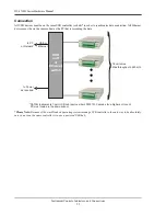
Use the removable screw terminal blocks located on the front of the instrument to connect your analog input signals.
Refer to the Screw Terminal Access sticker on the top of the instrument for pinout.
1. Insert the stripped end of a signal lead into the desired terminal directly under the screw.
2. Tighten the pressure flap by rotating the screw clockwise with a small screwdriver. Make sure that the pressure
flap tightens only against the signal wire and not the wire insulation.
Do not over-tighten.
3. Tug gently on the signal lead to ensure that it is firmly secured.
When an input signal is connected and W
IN
D
AQ
Acquisition software is run, W
IN
D
AQ
’s real time display immedi-
ately reveals the input waveform on your computer’s monitor.
Low-pass Filter
Each analog channel employs a low-pass filter with automatic corner frequency selection. The filter is a CIC (cas-
caded integrator comb) type that uses as many as 512 samples per channel to calculate in real time as data is acquired.
Filter response is optimized when sampling frequency is set to ten times the highest frequency of interest.


