DI–4718B Series Hardware Manual
Instrument Controls, Indicators, and Connections
11
9. After all modules are installed and indicated on the sticker reassemble the instrument making sure not to over-
tighten the front screws.
Note: If your are installing a thermocouple module you must enable the Cold Junction
Compensation jumper for that channel (see “Enabling CJC for Thermocouple Modules” section below for more
information).
Enabling CJC for Thermocouple Modules
Enable Cold Junction Compensation for each Thermocouple Input module installed. The CJC Enable Jumpers are
located on the circuit board of the instrument.
Note: If you are not using a Thermocouple Input Module on that chan-
nel be sure the jumper is disabled (removed or installed on only one pin) because this will affect the input signal.
Each channel has its own CJC enable jumper located in front of each channel position on the instrument circuit board.
1. Unplug the device and make sure there is no power to the instrument.
2. Remove the front panel and bezel by removing the two screws on the front of the instrument.
3. Remove the ground lug from the back of the instrument.
4. Pull the circuit board apart from the casing to reveal the CJC Enable Jumpers.
5. Install a jumper onto the board for each channel that uses a thermocouple module. Eight jumpers are provided
with the DI-4718B for this purpose.
Note: If you are not using a Thermocouple Input Module on that channel be sure the jumper is disabled (removed
or installed on only one pin) because this will affect the input signal.
6. After the DI-8B modules and jumpers are installed reassemble the instrument making sure not to overtighten the
two front screws.
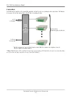
CHANNEL 8
CHANNEL 5
CHANNEL 4
CHANNEL 1
CHANNEL 2
CHANNEL 3
CHANNEL 6
CHANNEL 7
CJC Enable Jumpers
Circuit Board with DI-8B Backplane
Casing
Front of DI-4718B

