Adjustments and Maintenance
2-16
2.
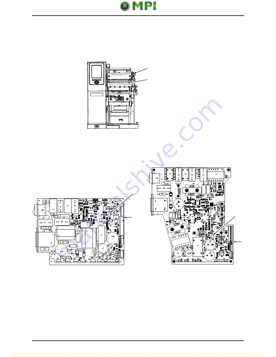
Remove the Cover (see Section 4.1 for details). Raise the
Printhead Assembly.
Locate the attached
Printhead Label
and note the resistance value of the printhead. Make sure that media is loaded in
the printer then lower and lock the
Printhead Assembly
.
Printhead Assembly
Printhead Label
3.
Locate the
Power Supply CCA
(see Section 4.7), then using a digital multi-meter (DMM) set to
measure DC voltage, probe
J2 - Pin 3
with the positive lead and
J2 - Pin 8
with the negative lead.
J2
RP1
Pin 1
J2
RP1
Pin 1
Short Model Potentiometer and J2 Location
Tall Model Potentiometer and J2 Location
4.
In the table below, locate the
Resistance
(found in Step 2). Turn ON the printer and wait breifly.
Press the
FEED Key
to temporarily enable (about thiry seconds) the voltage. Using
RP1
(see
illustration above) adjust the
Voltage
.


