background image

46  

  Appendix 

Ahiba IR Pro User's Guide 

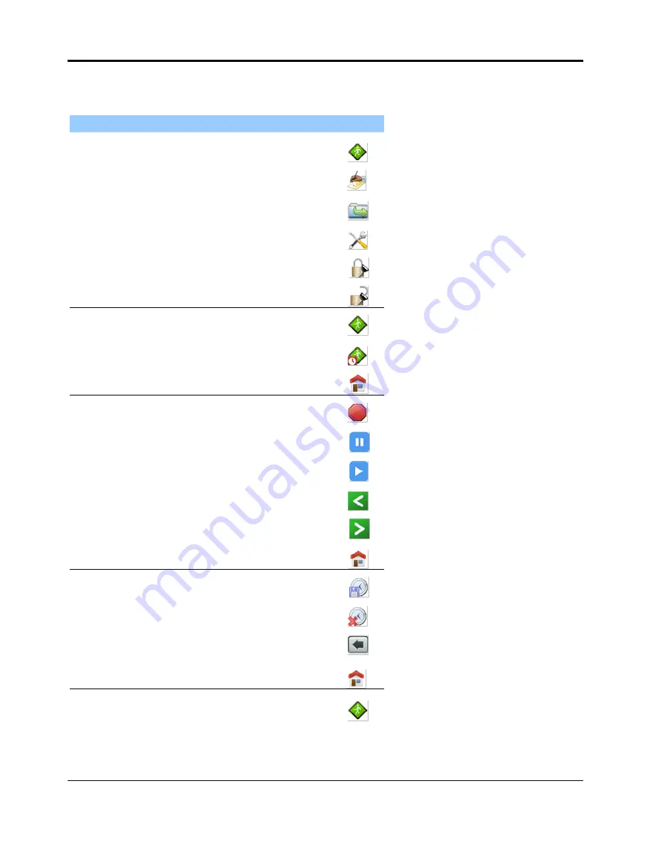
Glossary of Icons 

Below are a listing of the screens on the Ahiba IR Pro controllers and the active icons on 
each screen. 

Screen 


Icon Use 

Icon 

Main menu

, “System Idle”   

Run Menu 


Manual mode 


Directory menu 


Tool menu 


Login 


Logout 


Run menu Screen 


Run Program 


Delayed Run 


Home Screen 


Process Running Screen   

Stop Program 


HOLD Program 


Continue Program 


Graph scroll left 


Graph scroll right 


Home Screen 


Delayed run screen 


Delay program save 


Delay program cancel 


Previous screen 


Home Screen 


Manual mode screen 


Run manual program 


Summary of Contents for AHIBA IR Pro

Page 1: ......

Page 2: ......

Page 3: ...visit our website at www datacolor com Support Questions If you need help with a Datacolor product please contact one of our top rated technical support teams located around the world for your convenience You can find contact information below for the Datacolor office in your area Americas 1 609 895 7465 1 800 982 6496 toll free 1 609 895 7404 fax NSASupport datacolor com Europe 41 44 835 3740 41 ...

Page 4: ......

Page 5: ...ment Controls and Indicators 9 Overview 9 Front of Unit 9 Inside of Unit 10 Back of Unit 10 Controller 11 System Setup and Maintenance 11 System Location 11 Power Connections 12 Water Connection 12 Main Power Connection 12 Controller Grounding Connection 13 Controller Power Supply 14 Beaker Preparation Cleaning and Maintenance 15 Beaker Installation 15 Beaker Dosing 19 Beaker Preparation Basket 20...

Page 6: ...a Program 35 Deleting a Program 36 Copy a Program 36 Save to External Memory 36 Load from External Memory 37 Running a Program 37 Program Hold 38 Hold Precautions and Tips 38 Manual Program Hold 38 Alarms and Status Messages 38 Audible Alerts 39 Troubleshooting Alerts and Alarms 40 Appendix 43 Specifications 43 Minimum Maximum Beaker Loads 44 Minimum Beaker Load 44 Maximum Beaker Load 44 Maintenan...

Page 7: ...IR Pro Overview Ahiba IR Pro is an infrared dyeing machine that handles a wide variety of processes in exhaust dyeing laboratories It can be used as an atmospheric or high temperature dyer The unit can also be used to simulate wash fastness testing ...

Page 8: ...ed temperature time sequences Microprocessor technology ensures that the controller accurately follows the pre defined dyeing curves The user interface employs an icon driven interface that helps eliminate all operator obstacles that exist with text driven interface designs A touch screen completes the data entry tools ...

Page 9: ... Protects the equipment and samples from overheating Type of Fibers All fibers Dyeing Positions Accommodates up to 20 dyeing positions Types of Substrates Piece Hank Combed Slivers Loose Material Liquor Ratio 1 3 Synthetics 1 5 Natural Wash Fastness Testing Unit can also be used to simulate wash fastness testing User Interface Icon and menu driven user interface Maximum number of custom programs s...

Page 10: ... the following Self refilling dosing syringe Accessories for membrane dosing Accessories for injection dosing These accessories can be ordered with the system or ordered at a later time See also Appendix Accessories List for details to order these accessories About the Beakers The Ahiba IR Pro can work with several different beaker sizes A standard unit includes a single set of beakers and the bea...

Page 11: ...f the sample and dyebath inside the beaker The number of beakers supplied is based on the number of dyeing positions ordered with the unit See also Appendix Optional Accessories in this guide for a complete list of optional accessories Safety Labels and Precautions The following symbols are found on the equipment and in the documentation Do Not Touch Surface is Hot There is a danger of burn injuri...

Page 12: ...The power cord must be plugged into an outlet with a protective grounding terminal Do not invalidate protection by using an extension cord without protective grounding CAUTION Turn main power switch to OFF and remove the power cord from the electrical outlet before any internal service work is done Use Precautions Unit is to be used only as laboratory dyeing equipment Continue operating only as lo...

Page 13: ...hey are mounted at the top of the unit The heat is transferred from the beaker to the dyebath liquor The design of the beakers ensures accurate beaker to beaker temperatures A reference beaker fitted with a temperature sensor is used to measure the dyebath temperature The actual temperature is reported to the controller via a rotary switch 2 high CFM blower fans are used to circulate air in the ch...

Page 14: ...R Pro Ahiba IR Pro User s Guide Beaker Rotation Rotation Speed 5 50 rpm selectable Beaker Movement Programmed reverse function reverses wheel direction in accordance with parameter set in dyeing program 0 9 min ...

Page 15: ... 9 Equipment Controls and Indicators Overview This section itemizes all of the controls and indicators included on the Ahiba IR Pro Front of Unit Controller Transparent glass panel with protective shield Insulated Cabinet Door Latch ...

Page 16: ...a IR Pro User s Guide Inside of Unit Back of Unit Door Closed Sensor Reference Beaker Beaker Wheel Dyeing Beaker Infrared Lamps 3 Water Inlet and Drain connections Main System Power Switch Over Temperature Reset Switch IR Lamp Circuit Breaker ...

Page 17: ...ding wire Connect main communication cable to the controller Connect unit to power source Connect to cold water supply and gravity drain Beaker installation System Location The Ahiba IR Pro should be placed on a stable level table The table should have sufficient height to allow for easy opening and closing of the door and easy viewing of the controller LED Status Panel Touch Screen Display USB In...

Page 18: ...ure 2 3 bar 30 45 psi Hardness 10 dH Temperature Ideally 15 C Hose Min diameter 3 8 10mm Hi Temp Main Power Connection You must connect the power cord of the unit to an electrical outlet or power box with proper earth grounding CAUTION The power connection should be made by a certified electrician INFORMATION Prior to connecting the Ahiba IR Pro unit ensure that the local line voltage agrees with ...

Page 19: ...ding Connection In order to protect the electronics in the controller box a grounding wire must be installed between the controller and the base unit This wire is provided for you Ensure the connections are tight See illustration below Grounding Points ...

Page 20: ... Fuse 15 A Controller Power Supply The Ahiba IR Pro controller is powered separately from the machine Before turning the controller on check that the power connection from the main power cord is completed and checked for correct voltage levels When you have verified the connection 1 Turn on the main power switch located on the lower back of unit 2 Locate the controller power switch on the rear of ...

Page 21: ...llowing steps Secure beaker lids This is done each time a dyeing process is run Install beakers Install connect reference beaker and sensor cable All of the steps described below must be performed for each dyeing cycle Securing the Beaker Lids Before the beakers are attached to the wheel the lids must be secured using the hex screwdriver supplied with the unit To secure the lids 1 Ensure beaker li...

Page 22: ...l Do not mix beaker sizes in a single process All beakers loaded on the wheel must be the same size The Ahiba IR Pro uses custom designed pressure tested beakers The seal between the beaker and the lid is accomplished with an O ring seal This O ring is a maintenance part and additional O rings are supplied with the unit Over tightening of the beaker will damage the O ring and cause damage to the l...

Page 23: ...erature as the reference beaker See also Appendix Beaker Loads for minimum and maximum beaker load specifications Beaker Connections Below are some guidelines to consider when connecting a beaker to the wheel The sensor lead is connected and locked to the beaker by the rotating collar of the sensor Continue turning the collar until the connection is locked To insure that the cable is locked to the...

Page 24: ...mperature sensor cable is plugged into the center of the drive shaft It is secured by a holding clamp This prevents accidental disconnection of the sensor from the plug The sensor should be connected to the reference beaker before installing the beaker on the beaker wheel It should be removed prior to removing the reference beaker when the dyeing is completed CAUTIONS Avoid pulling hard on the tem...

Page 25: ... of the installation of the manual dosing protector INFORMATION When dosing a beaker the liquid chemical being dosed should not come into direct contact with the substrate All dosing beakers are fitted with a dosing protector which diffuses the flow of the liquor onto the substrate This prevents the substrate from being directly contacted with the chemical Thoroughly rinse the injection nipples wi...

Page 26: ...osing capsules with new O rings and springs over time additional spares are supplied with the system Beaker Preparation Basket The Ahiba IR Pro comes standard with a beaker preparation basket with each unit This is included with your unit it must be assembled Directions for assembly are supplied See also Accessories Beaker Preparation Basket for a picture Beaker Cleaning and Maintenance All beaker...

Page 27: ...ure screen So use reasonably delicate touch with it Don t use tap water or mineral water as they could leave white marks on the screen because of the dissolved salts Don t use paper towels or any type of cloth that is not lint free as they can leave residue or even scratch the display Don t spray liquid directly on the screen Apply liquid to a cloth and then wipe the screen Don t use Windex or any...

Page 28: ......

Page 29: ...n the background ensuring the proper operation and control of the process When an error occurs the controller communicates the error via text status messages display color change LED light and audible alarms The Ahiba IR Pro works with stored programs that contain customized time and temperature dyeing sequences The unit can hold a maximum of 99 programs each having a maximum of 15 steps A stored ...

Page 30: ...efault setting for operator allows only running of stored processes and manual mode operation The following sections will describe operations as an operator and later as an administrator Operator By default for an operator the Ahiba IR Pro will allow access to 3 main screens Run Program Screen Run Manual Mode Screen Program Directory Screen System Idle Screen The Main Menu or System Idle screen is...

Page 31: ...ce the screen by one page at a time to access all 99 program slots Programs are sorted by the program number assigned at the time the program was created Pressing the Home button will drive to the system idle screen Process Running Screen The Process Running Screen will display as below all the parameters for a program Page Advance Buttons Home button Visual Process Icon Graph advance home button ...

Page 32: ...eters of the programmed step END Process A button to END or stop the process Pressing this will be followed by a confirmation screen HOLD Process A button to put the unit into a manual HOLD step The temperature will remain as it is at the time HOLD is pressed until a CONTINUE button is pressed Visual Process Icon Icons visible on all screens of the controller while a program is running If you leav...

Page 33: ...ogram run simply press the cancel button and the process is stopped INFORMATION While the IR Pro is running in Delayed Program Run no other programs can be started All monitoring systems are operating The beaker wheel will turn at 5rpm during the delayed run to help agitate the beakers Run Manual Mode Screen The Ahiba IR Pro offers a unique ability to input a quick single step program called Manua...

Page 34: ... 99 program slots Page advance buttons on the right side allow you to advance to other pages In operator mode all functions are grayed out except RUN You must be logged in as administrator or have been given rights by the administrator to access the other functions allowed on this screen LED Indicators LED indicators are located on the left side of the controller These are used to communicate spec...

Page 35: ...of the actual performed dyeing curve compared with the programmed curve time and date stamp of each reading The read interval will be every one minute Administrator The IR Pro offers lab managers the flexibility of assigning task or limiting operators ability to perform certain functions If you are logged in as administrator you will have access to perform all task and functions on the Ahiba IR Pr...

Page 36: ... More detail of how to perform tasks will be described later Local Memory In the local memory you can Delete an existing program from the local memory Delete ALL local memory Save a local program to the external flash drive for back up or transfer to another unit Copy a program from one memory location slot to another RUN an existing program Edit and existing program or create a new program Extern...

Page 37: ...st the controller to display all temperatures in C or F It also allows you to adjust the date and time and format of the date and time display Password Setup is an icon that allows you assign your unique 4 digit numeric password Language is an icon that allows you to select one of the 7 available languages English German French Spanish Portuguese Italian or Chinese The text under each icon will ch...

Page 38: ......

Page 39: ...ned a temperature gradient time rotation speed reverse rotation and process HOLD A process HOLD is generally used when the program requires operator intervention A hold can be included as a program step or can be inserted manually at run time See also Running a Program Program Holds for a detailed discussion of this option Limit Values When entering data for a program all entries are checked again...

Page 40: ...e already assigned for certain areas To gain access to an area simply touch the area and it will highlight and a numeric keypad will display so data can be entered Pressing enter will save that data Temperature control icon Provides control to the temperature input line Gradient control icon Provides control to the gradient input line Time control icon Provides control to the time input line Motor...

Page 41: ...u wish to edit the data Touch and highlight the area you wish to change the data and a keypad will appear to enter the data After all cahnges are made press to save your changes 5 In the program edit section you have the ability to insert a new step or delete a step of a given program o To Insert a step use the icons to get to the step you want to insert a step at and press insert step icon and a ...

Page 42: ... pressing yes will delete ALL programs stored in the external memory Copy a Program Is a function on the IR Pro controller that allows you to make an exact copy of an existing program in a different program slot From the program directory screen you can highlight a program and then press the copy icon and assign your copied program to a new program slot A confirmation menu will appear If you try t...

Page 43: ... any time by pressing the STOP button CAUTION Do not unplug the bayonet sensor from the reference beaker when a program is running The temperature will drop very quickly activating temperature monitoring and the program will stop running 1 From the System Idle screen press the icon The Program Directory screen displays Press and highlight the program number you wish to run and then press the run i...

Page 44: ...icon and the display will return to normal and the next step in the program will advance Hold Precautions and Tips When a hold is enabled and the door opened the IR lamps are turned off and the motor stops turning As a result the temperature inside the beaker drops You should limit the time the door is open Manual Program Hold The operator can manually place a hold on the program To do this Press ...

Page 45: ...there is an audible alert pressing the alarm silence icon will silence the alarm It will not clear the alarm LED Panel Below is a key for these symbols Indicator Function Power On When controller is powered on this indicator is solid green Process Running When a process is running this indicator is flashing blue Alarm When controller detects an alarm this indicator is solid red Process Hold When a...

Page 46: ...ure variation returns to within 5 C the alarm will reset The buzzer will stop 2 During a heating or cooling cycle in the program the system has detected a temperature variation of 15 C The program must be re started at step 1 after the problem is corrected 3 Controller has detected either a PT 100 open or PT 100 short circuit PT 100 open The screen displays a temperature of 350 When temperature is...

Page 47: ...ops for more than 2 minutes this alarm triggers The system will stop heating and the program will stop Program must be restarted from step 1 Alarm will reset and alarm icon will disappear when the wheel starts turning again Defective motor Defective motor position switch defective reversing circuit on power interface card Power Interruption Continuous alarm sounds Red Alarm LED lights Message is d...

Page 48: ...red by the operator A Status Message appears Program Halted Operator Action Required Press Continue icon and the program will continue or advance to the next step Other general information messages will display in the Status area This area is used to relay information to the operator about the success or failure of certain functions Some of these messages include Program Saved Successful Program D...

Page 49: ...m x 330mm 19 7 x 17 7 x13 Weight 74 Kg 163 lbs Electrical Supply 230V AC 10 50 60 Hz Heating Power 3000 W Total Power 3300 W Total current IR PRO 14A Protection Breaker L1 L2 16A Fuse N L1 20A Operating Temperature 5 C to 40 C Environmental 80 max relative humidity up to 31 C 50 relative humidity up to 40 C Approvals TUV CE Specifications subject to change without notice ...

Page 50: ...ize Minimum No of Beakers 150cc 6 beakers 300cc 4 beakers 500cc 4 beakers 1000cc 4 beakers Maximum Beaker Load Beaker Sizes max Maximum of Beakers Ideal Sample Size 150 ml 20 beakers 5 grams 300 ml 15 beakers 10 grams 500 ml 8 beakers 25 grams 1000 ml 8 beakers 50 grams 5 liter 1 beaker 250 grams ...

Page 51: ... and shiny in order to maximize reflection User x Dyeing Beaker Check for leaks Replace O ring if necessary User x Drive Check belts and listen for drive noise If necessary adjust or replace belts Datacolor Service x Speed of the Drive Check and calibrate if necessary Tolerance 2 rpm Datacolor Service x Temperature Calibration Check the temperature calibration and adjust if necessary Tolerance 1 C...

Page 52: ...Icon Main menu System Idle Run Menu Manual mode Directory menu Tool menu Login Logout Run menu Screen Run Program Delayed Run Home Screen Process Running Screen Stop Program HOLD Program Continue Program Graph scroll left Graph scroll right Home Screen Delayed run screen Delay program save Delay program cancel Previous screen Home Screen Manual mode screen Run manual program ...

Page 53: ... local Memory View ext Memory View History local View Local menu Screen Delete Program Delete All Programs Edit Program Save External Copy Program Run Program Previous screen Home Screen Login Logout View Ext menu screen Load ext Memory Delete Program Delete All Programs Previous screen Home Screen View history local Previous Screen ...

Page 54: ...cal Home Screen Edit info menu Previous Screen Home Screen Enter Edit program screen New Step Insert Step Delete Step Save Changes Previous step Next step Temperature Gradient Isotherm time RPM CW CCW Hold Previous Screen Home Screen Tool Screen Configuration menu user setup ...

Page 55: ...e Setup Language Passcode setup Operator access Previous Screen Home Screen Temp time setup Save Changes Previous Screen Home Screen Passcode Save Changes Previous Screen Home Screen Language Save Changes Previous Screen Home Screen Operator access Save Changes Previous Screen Home Screen ...

Page 56: ...er s Guide Accessories Beaker Preparation Basket A beaker preparation basket is available with the unit You must assemble it Below is an assembly diagram Below is a picture of a fully loaded beaker prep basket Beaker Prep Basket ...

Page 57: ...e parts extends the life of the seals and prevents clogging due to dried chemicals Below is information for ordering replacement parts from Datacolor for the dosing syringe Drawing Position Description Part No 10 20 30 40 50 60 70 10cc Dosing Injector Dosing Injector 10cc Glass cylinder 10cc Seal to injector Valve Ball Valve Spring Dosing Adapter Teflon Seal 474070 474077 474080 474082 474081 4740...

Page 58: ...the dosing capsules with warm water following each use This cleans the interior of the parts extends the life of the seals and prevents clogging due to dried chemicals Below is information for ordering replacement parts from Datacolor for the dosing capsules Description Part No Capsule Cap Complete Pack of 25 Springs Capsule to Lid Seal pack 25 Under Lid Cap Under Lid Cap O ring pack 25 Capsule Ho...

Page 59: ...5 Beakers 4 C Controller 22 Controller Power Supply 14 Controls 9 Cooling 7 Cooling Source 3 D Dosing Accessories 49 Dyeing Positions 3 E Equipment 9 H Heating 7 Heating Source 3 I Indicators 9 L LED Process Indicators 26 Limit Values 31 Liquor Ratio 3 M Maintenance 11 43 N Numeric Keypad 27 O Operating Principles 7 P Power Connections 12 Precautions 5 6 chemical handling 7 electrical 6 environmen...

Page 60: ...ectory 26 28 Programs 31 S Safety Labels 5 Specifications 41 Status Messages 37 System Idle 22 System Location 11 System Setup 11 T Temperature Monitoring 3 Temperature Sensor Cable 18 Troubleshooting 38 Type of Fibers 3 Types of Substrates 3 U User Interface 3 22 W Wash fastness Testing 3 ...

Reviews: