


USB3-FRM13 User’s Manual
16
USB3-FRM13
OUT
TTL(3.3V)
Line Drive
Encoder
Encoder IN
Line Driver
PHOTO
FPGA Core Logic
Camera
Motion Controller
Or
Digital I/O
bit0(CC1 configure) = “0” : digital out1 / “1”: alternate (Trigger1 output)
bit1(CC2 configure) = “0” : digital out2 / “1”: alternate (Trigger2 output)
bit2(CC3 configure) = “0” : digital out3 / “1”: (Digital output)
bit3(CC4 configure) = “0” : digital out4 / “1”: alternate (Reference clock output)
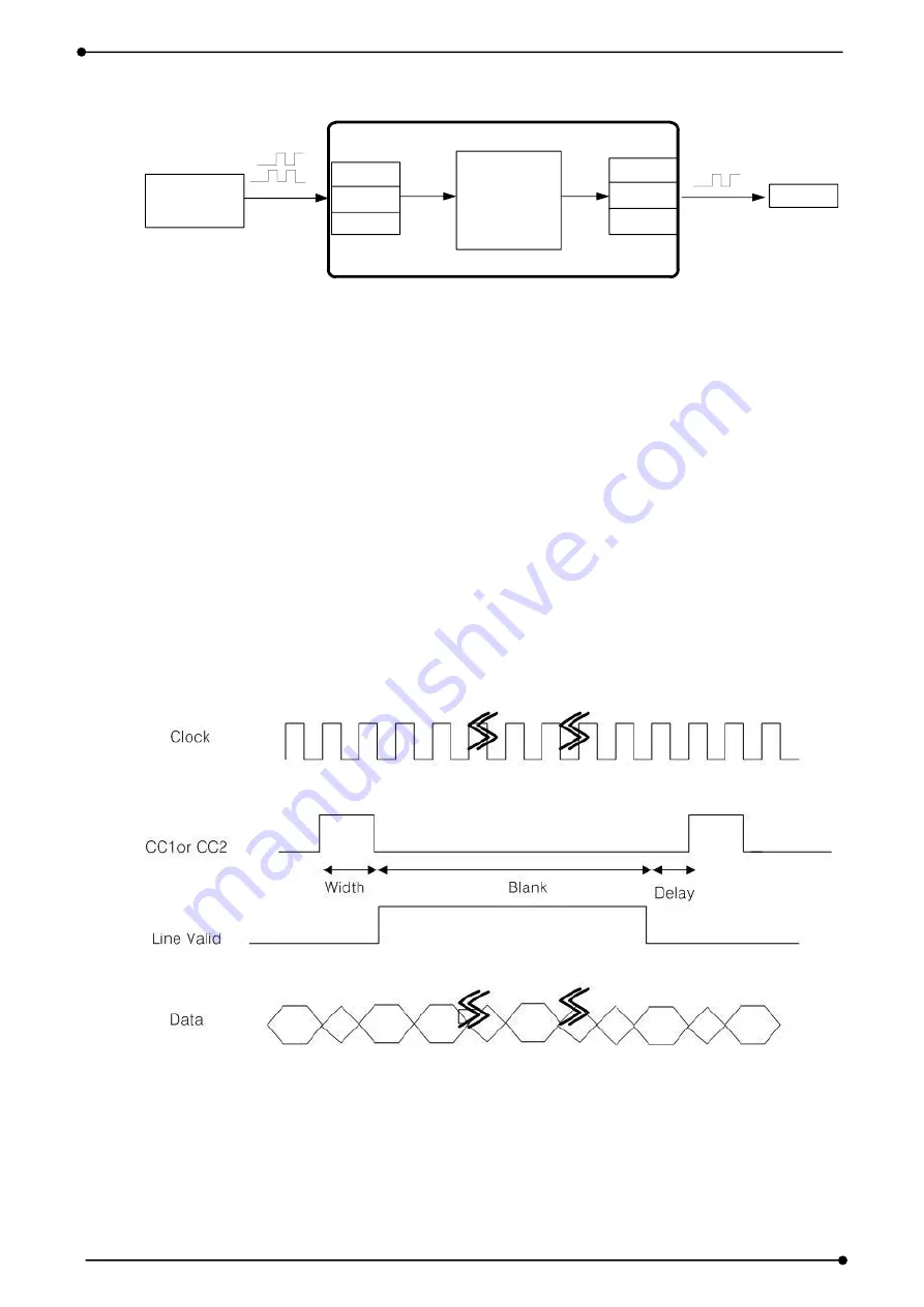
The Line Scan Camera is less time to transfer the information rather than Area Scan
Camera because the outputs are a single line of pixels per exposure. However, the Line
Scan Camera will be required moving objects in order to obtain images. Synchronization
between the movements of the camera and the object is required. This synchronization is
a little difference according to the manufacture’s cameras and is performed by the trigger
pulse which most of the triggering signal of an external camera or the camera’s itself. The
trigger pulse is initiated by the application. A thickness, width, delay of the trigger can be
gave a value (Blank, Width, Delay) by the program.
[Figure 2-14. Trigger Timing]


