Dante DNA1991YM Operation User'S Manual Download Page 70


36


When the “Mode” is set as “Auto”, the system can auto compensate white balance upon different 

color temperatures, which is to make the image color normal.  


When the “Mode” is set as “Natural”, the system can auto compensate white balance to the scene 

without artificial light, which is to make the image color normal.  


When the “Mode” is set as “Street Lamp”, the system can auto compensate white balance to the 

outdoor scene at night, which is to make the image color normal.  


When the “Mode” is set as “Outdoor”, the system can auto compensate white balance to the most 

outdoor scenes with natural light and artificial light, which is to make the image color normal.  


When the “Mode” is set as “Manual”, it can manually set the value of red gain and blue gain; the 

system can compensate the different color temperatures in the environment according to the 

settings.  


When the “Mode” is set as “Regional Custom”, it is to set customized area, the system can 

compensate white balance to different color temperature of the images in the area, which is to 

make the image color normal.  


Step 3  

Click “Save” to complete the config of WB mode.  


5.1.1.5 

Day & Night  

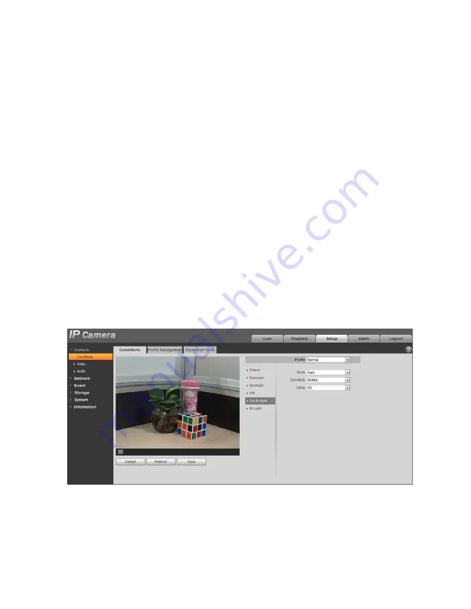
It is to set the switch between color mode and black & white mode.  

Step 1  

Select “Setup > Camera > Conditions > Day & Night” and the system will display the interface of “Day & 

Night”, which is shown in Figure 5-5.  


Figure 5-5 


Summary of Contents for DNA1991YM

Page 1: ...DNA1991M IP IR PTZ Domes Operations User Manual Model Number DNA1991YM Description IP MP IR PTZ Domes 20X 30x Optical Zoom With Intelligent Analytics...

Page 2: ...d Rate Setup 3 Speed Dome Address Setup 3 Dial Switch Setup HDCVI Speed Dome 3 Dial Switch Description 3 HD SD Video Format Setup 4 Baud Rate Setup 4 Speed Dome Address Setup 4 Reset and SD Card Insta...

Page 3: ...2 Installation Requirements 14 Installation Steps 14 5 5 1 5 2 5 3 5 4 6 7 7 1 7 2 7 3 BRACKET DIMENSIONS 16 Wall Mount Bracket 16 Hanging Mount Bracket Multiple Lengths 16 Corner Mount Bracket 17 Po...

Page 4: ...7 4 8 RS485 Bus FAQ 20 APPENDIX SAFETY ROPE INSTALLATION 21 iii...

Page 5: ...Welcome Thank you for purchasing our speed dome Please read the following safeguards and warnings carefully before you install or use the product iv...

Page 6: ...reach the installation height The lifting appliances shall have safe performance The precaution measures include two types Warning and Note Warning It is to alert you there is an optional risk of deat...

Page 7: ...the device There is risk of personal injury or device damage resulting from opening the shell Please contact your local retailer if there is internal setup or maintenance requirement We are not liable...

Page 8: ...o clean the shell and then use soft cloth to make it dry Do not use gasoline dope thinner or other chemical material to clean the shell It may result in shell transfiguration or paint flake Do not all...

Page 9: ...We assume no liability or responsibility for all the fires or electrical shock caused by improper handling or installation Check installation space and installation location intension Please make sure...

Page 10: ...l switch buttons on the PCB of one side of the speed dome There are labels User may use them to set speed dome baud rate address and etc See Figure 1 1 It is 1 when you set the button as ON For the pr...

Page 11: ...FF OFF OFF OFF 5 ON OFF ON OFF OFF OFF OFF 6 OFF ON ON OFF OFF OFF OFF 7 ON ON ON OFF OFF OFF OFF 1 3 2 Parity Setup Please refer to the parity setup sheet for detailed information 1 3 3 Baud Rate Set...

Page 12: ...he setup be valid Note The IR speed dome can automatically recognize the PELCO D PELCO P and industry standard protocol control protocol doesn t need to be set via dial Figure 1 2 1 4 2 HD SD Video Fo...

Page 13: ...etwork Speed Dome User may see there are a RESET button dial switch button and Micro SD card slot on one side of the PCB of the speed dome See Figure 1 3 It is 1 when you set the button as ON RESET bu...

Page 14: ...re the wall thickness can sustain the expansion bolt The wall can support at least the 8X of the speed dome weight 1 6 3 Dig Installation Holes Draw the installation holes in the wall according to the...

Page 15: ...Step 2 Cable connection Connect the video RS485 power Network alarm audio and optical fiber are optional to the corresponding ports Please note the cable description here is for reference only Step3...

Page 16: ...tion wall in the indoor or outdoor environments Before the installation please make sure The wall is thick enough to install the expansion bolt The wall can at least sustain the 8x weight of the speed...

Page 17: ...se note the cables listed here is for reference only Use the quick installation screw of the speed dome and the quick instillation port of the adapter block to fix the speed dome on the adapter block...

Page 18: ...straight pole of the bracket See Figure 2 5 Figure 2 5 Step 3 Connect cable and the speed dome Connect the safety rope of the speed dome to the safety rope hole of the adapter block Now you can connec...

Page 19: ...stalled in the outdoor environments you need to paste enough Teflon tape at the top screw thread of the steeve and then turn the steeve to the flange firmly Please paste the silica gel on the steeve c...

Page 20: ...grees angle Before the installation please make sure The wall is thick enough to install the expansion bolt The wall can at least sustain the 8x weight of the speed dome 3 2 2 Installation Steps Step1...

Page 21: ...Figure 3 3 13...

Page 22: ...ole structure shall comply with the installation dimension of the clamp 4 1 2 Installation Steps Step 1 Fix bracket and the pole Install clamp and then pole mount bracket Pull the cable out of the pol...

Page 23: ...Figure 4 3 15...

Page 24: ...NSIONS 5 1 Wall Mount Bracket The wall mount bracket dimensions are shown as below See Figure 5 1 Figure 5 1 5 2 Hanging Mount Bracket Multiple Lengths The hanging mount bracket is shown as below See...

Page 25: ...Figure 5 2 5 3 Corner Mount Bracket The corner mount bracket is shown as below See Figure 5 3 Figure 5 3 5 4 Pole mount bracket The corner mount bracket is shown as below See Figure 5 4 Figure 5 4 17...

Page 26: ...int to the earth Open floor cable layout is forbidden In area of strong thunderstorm hit or near high sensitive voltage such as near high voltage transformer substation you need to install additional...

Page 27: ...too much devices connected to the RS485 bus And vice versa the max transmission distance shall become longer 7 3 The Problem in Practical Use In practical usage we usually adopt star type connection T...

Page 28: ...are cut off Modify host or speed dome setup Switch RS485 positive end and negative end Fix connection cable firmly Replace RS485 Bus I can control the speed dome but is not smooth RS485 Bus connectio...

Page 29: ...M4 Screw of the Speed Dome Note Safety Rope This manual is for reference only Slight difference may be found in the user interface All the designs and software here are subject to change without prio...

Page 30: ...i Network Camera Web3 0 Operation Manual Version 1 0 1...

Page 31: ...5 Fluency Adjustment 10 2 4 6 Rules Info 10 2 4 7 Zoom and Focus 10 2 4 8 Fisheye Trigger Track 10 3 PTZ Control 15 3 1 Scan 16 3 2 Preset 17 3 3 Tour 17 3 4 Pattern 18 3 5 Assistant 19 3 6 Light Wip...

Page 32: ...3 802 1x 73 5 2 14 QoS 74 5 2 15 HTTPs 75 5 3 Event 85 5 3 1 Video detection 85 5 3 2 Audio Detection 92 5 3 3 Smart Plan 94 5 3 4 Intelligence Behavior Analytics 94 5 3 5 Face Detection 102 5 3 6 Peo...

Page 33: ...iv 5 5 6 Remote control 131 5 5 6 Auto Maintenance 132 5 5 7 Upgrade 133 5 6 Information 133 5 6 1 Version 133 5 6 2 Log 134 5 6 3 Online User 134 6 Alarm 136 7 Log out 138...

Page 34: ...v Important The following functions are for reference only Some series products may not support all the functions listed below...

Page 35: ...a the Internet you need to have its IP address User can use Config Tool to search IP of the network camera Please refer to Config Tool manual 1 2 Log in It needs to install WEB plug in when you use WE...

Page 36: ...ame and password Default factory username is admin and password is admin Figure 1 3 The system will display Update Password prompt box for your first login users need to modify the password and save i...

Page 37: ...3 Figure 1 5 Click on Please click here to download and install the plug in The system pops up warning information to ask you whether run or save this plug in See Figure 1 6 Figure 1 6...

Page 38: ...4 You must either run or save the file to local and install it Follow the following steps Click on run you will see Figure 1 7and Figure 1 8 Figure 1 7...

Page 39: ...5 Figure 1 8 When plug in installation completes the installation page closes automatically The web end will refresh automatically and then user may view video captured by the camera Figure 1 9...

Page 40: ...ons Section 1 Encode setup bar Section 2 System menu Section 3 Window function option bar Section 4 Window adjust bar 2 1 Encode Setup Note Some series don t support sub stream 2 The encode setup inte...

Page 41: ...ocol User may select stream media protocol from the dropdown list There are three options TCP UDP Multicast 2 2 System Menu System menu is shown as in Figure 2 3 Please refer to chapter 2 Live chapter...

Page 42: ...ages are saved to path in Ch 5 1 2 5 5 Record Click it to record the video All videos are saved to path in Chapter 5 1 2 5 6 Easy focus Click it user may see there are two parameters on the preview vi...

Page 43: ...go to Setup Camera Conditions to adjust corresponding items It is to adjust monitor video contrastness It is to adjust monitor video hue It is to adjust monitor video saturation Reset Restore brightne...

Page 44: ...eview interface as shown in Figure 2 7 click left mouse button to adjust focus zooming configuration Note The product series which support motorized zoom synchronous focus and back focus have this but...

Page 45: ...e image definition automatically Note Other lens operations are not allowed during the process of auto focus Reset All Reset the lens to zero position to eliminate the accumulative error of lens Note...

Page 46: ...ded rectangular panorama also supports left and right starting point movement 2P Two related 180 expanded rectangular pictures two subwindows form 360 panorama anytime which is also called dual panora...

Page 47: ...nd changes vertical angle of view 1P 4 180 expanded rectangular panorama 4 independent sub images both the sub images and the sub box in the expanded rectangular panorama support zoom and movement exp...

Page 48: ...trigger track windows it can adjust the location and size of three trigger track windows on the original picture 1P 5 Original picture and five trigger track windows it can adjust the location and siz...

Page 49: ...Currently only IPC HFXXXX series and PT series products can support PTZ function Parameter Note PTZ direction PTZ supports eight directions left right up down upper left upper right bottom left botto...

Page 50: ...2 PTZ setting interface is shown as in Figure 3 3 Here user may set scan preset tour pattern assistant function and light and wiper plus view coordinate Figure 3 3 3 1 Scan Scan interface is shown in...

Page 51: ...on Set Right to set right border of camera Step 4 Complete scan path setup 3 2 Preset Preset interface is shown in Figure 3 5 Figure 3 5 Steps to preset are Step 1 In preset box input preset value Ste...

Page 52: ...his tour If click on Del it deletes this preset in tour Note User may add more than one preset here or delete more than one preset 3 4 Pattern Pattern interface is shown in Figure 3 7 Figure 3 7 Steps...

Page 53: ...sistant interface is shown in Figure 3 8 Figure 3 8 Steps to assistant are Step 1 In assistant box input assistant value Step 2 Click on Aux On to turn on aux function Click on Aux off to turn off aux...

Page 54: ...ser shall set storage management as in Ch 5 4 4 1 Playback The playback interface is shown as in Figure 4 Figure 4 1 There are four sections Section 1 Function of play Section 2 Playback file Section...

Page 55: ...ction Slow Click on this button to play slowly Quick Click on this button to play quickly Silent When this button displays it means audio is silent Click on this button to switch back to normal Volume...

Page 56: ...ime axis displays record file progress bar in color While green represents normal record yellow represents motion detect record red represents alarm record and blue represents manual record Step 2 Cli...

Page 57: ...ans records within searched start time and end time on the date Record Format There are two formats dav mp4 Download Click the download button and download file to path in Ch 5 1 2 5 System does not s...

Page 58: ...cur icon as finish cutting Step 3 Click on playback cut end time on time axis This time must be within progress bar range Step 4 Move mouse to cut icon you will be asked to select end time Click on c...

Page 59: ...Digital Zoom Click on it video in playback status if is in original size user can zoom in any area If it is not in its original size right click mouse to restore its original size Click on this button...

Page 60: ...26 Figure 4 11 4 2 1 Play Figure 4 12 Default icon is and it means pause or not played picture Click on play button to switch to normal play status Icon become Click on it to pause 4 2 2 Playback File...

Page 61: ...1 Click on file list select snapshot file of the date Step 2 Double click on file in list to play this snapshot Parameter Function Search It means all snapshot files within the start time and end tim...

Page 62: ...wnload Click the download button to open snapshot file or directly download to local according to the browser types Back Click on back button to return to calendar interface and re select time Figure...

Page 63: ...After checking snapshot file type in file list only display file of selected type Users can also select the snapshot type to be displayed via the dropdown box above the file list See Figure 4 Figure 4...

Page 64: ...o the actual product for more details 5 1 1 1 Picture Note The device which supports true WDR fails to support long exposure when true WDR is enabled Step 1 Select Setup Camera Conditions Picture and...

Page 65: ...es the image is likely to generate noise more easily when the value is set too big Gamma It is to change image brightness and improve the dynamic display range of the image via nonlinear adjustment mo...

Page 66: ...more details Parameter Note Anti flicker Outdoor User may switch to exposure mode when it is in outdoor mode it can realize the result in the corresponding exposure mode 50Hz When the current is 50Hz...

Page 67: ...ils to reach the effect and the shutter value has reached to upper limit or lower limit which is to make the image reach the best brightness Iris priority Iris value is fixed the device can auto adjus...

Page 68: ...pshot the human face in the dark environment and it can realize better effect for the details of the plate number Step 1 Select Setup Camera Condition Backlight the system will display the interface o...

Page 69: ...be video loss of a few seconds when the camera is switched from non WDR mode to WDR mode When the Mode is set as HLC the system will constrain the brightness of the area with high brightness and decre...

Page 70: ...nes with natural light and artificial light which is to make the image color normal When the Mode is set as Manual it can manually set the value of red gain and blue gain the system can compensate the...

Page 71: ...he parameter can be set when the Day Night Mode is Auto It is to set the sensitivity of the switch between image color display and black white display Delay The parameter can be set when the Day Night...

Page 72: ...ht mode user may set manual or auto When the Mode is set as Auto the system will auto adjust the image definition according to the actual scene When the Mode is set as Off then the defog function is d...

Page 73: ...enable the far light when the near light fails to meet the requirement of scene brightness even if it is adjusted to the brightest The system will adjust far light brightness by priority to off and th...

Page 74: ...nfig of always enable Figure 5 9 When the Profile Management is set as Schedule user may set some period as day and another period as night for example if it sets 0 00 12 00 as day 12 00 24 00 as nigh...

Page 75: ...t is focused set Speed and press or drag the sliding block directly to adjust Note Speed is used to set the length by pressing and After adjusting the focal length of the lens or click Auto Focus the...

Page 76: ...2 5 1 2 1 Video Step 1 Select Setup Camera Video Video and the system will display the interface of Video which is shown in Figure 5 12 or Figure 5 13 Figure 5 12 Non fisheye Figure 5 13 Fisheye Step...

Page 77: ...itched successfully The record mode will change according to the different installation modes 1O the original picture which is not dewarped 1P 360 rectangular panorama 2P The mode can be set when the...

Page 78: ...and you need to enable the sub stream function in your camera and set the resolution as CIF Then user may monitor via the Blackberry cell phone The H 265 is the main profile encode mode MJPEG In this...

Page 79: ...Here user may set the P frame amount between two I frames The value ranges from 1 to 150 Default value is 50 Recommended value is frame rate 2 Watermark Settings Select Watermark Setting and enable wa...

Page 80: ...on and clip the needed image on the interface which is shown in Figure 5 15 4 Click Save User may check the clipped video in the preview interface the sub stream 2 preview interface only displays the...

Page 81: ...Figure 5 15 Step 3 Click Save to complete video stream setup 5 1 2 2 Snapshot The snapshot interface is shown as in Figure 5 16 Figure 5 16 Please refer to the following sheet for detailed informatio...

Page 82: ...vation Image size It is the same as the resolution of main stream Quality It is to set the image quality There are six levels Interval It is to set snapshot frequency Optional1 7s picture customized 5...

Page 83: ...49 Figure 5 18 Figure 5 19...

Page 84: ...50 Figure 5 20 Figure 5 21...

Page 85: ...nnel tile position Text Overlay User may enable this function to overlay text in video window User may use the mouse to drag location box to adjust its position Alignment include align left and align...

Page 86: ...me title location overlay and save the change User may click on Refresh to see effect Default Click it to restore default config Save Click it to complete video settings 5 1 2 4 ROI Note Some series d...

Page 87: ...ord storage path The default monitor image path is C Users admin WebDownload LiveSnapshot The default monitor record path is C Users admin WebDownload LiveRecord The default playback snapshot path is...

Page 88: ...etwork transmission stream is the audio video composite stream otherwise it only includes video image Encode mode The encode mode of the main stream and extra stream include G 711A G 711Mu G 726 and A...

Page 89: ...evant noise Microphone Volume Adjust microphone volume from 0 100 Note Supported by some devices Speaker Volume Adjust speaker volume from 0 100 Note Supported by some devices 5 1 3 2 Alarm audio Figu...

Page 90: ...ddress WEB will automatically jump to the new IP address Figure 5 29 Please refer to the following sheet for detailed information Parameter Function Host Name It is to set current host device name It...

Page 91: ...dress Set the network camera and the PC in the same LAN Step 2 Get the physical address from the label of the network camera Step 3 Go to the Run interface and then input the following commands arp s...

Page 92: ...58 Figure 5 30 5 2 2 Connection 5 2 2 1 Connection The connection interface is shown as in Figure 5 31 Figure 5 31 Please refer to the following sheet for detailed information...

Page 93: ...rry need to set encode mode to H 264B resolution to CIF and turn off audio URL format is rtsp username password ip port cam realmonitor channel 1 subtype 0 Username password IP and port The IP is devi...

Page 94: ...ter it is enabled after it is successful the IP of the IP Address will be automatically modified into the dynamic IP address of the acquired WAN Note After PPPoE dial up is successful it needs to log...

Page 95: ...he device connects to WLAN you should disable UPnP Figure 5 34 Please refer to the following sheet for detailed information Parameter Function Server Type Click it to select DDNS protocol type which i...

Page 96: ...ult server address is www 3322 org Domain Name Self defined domain name Username The user name you input to log in the server Password The password you input to log in the server Refresh Period The re...

Page 97: ...hese addresses before enabling the trusted sites Please note You must set MAC address in the same network segment Figure 5 36 5 2 6 SMTP e mail The SMTP interface is shown as in Figure 5 37 Figure 5 3...

Page 98: ...e abnormity event activates the email system sends out the email according to the interval you specified here This function is very useful when there are too many emails activated by the abnormity eve...

Page 99: ...ort mapping without user modification Figure 5 38 5 2 8 SNMP The SNMP interface is shown as in Figure 5 39 and Figure 5 40 The SNMP allows the communication between the network management work station...

Page 100: ...from 1 to 65535 The default value is 161 Community It is a string as command between management and proxy defining a proxy and a manager s authentication Read community Read only access to all SNMP ta...

Page 101: ...art Parameter Function SNMP Version SNMP v3 Read only Username Default is public Note Name only can be number letter and underline Read Write Username Default is private Note Name only can be number l...

Page 102: ...t this function Click the Display All Bookmarks and open the Bonjour system can auto detect the network camera of the Bonjour function in the LAN Figure 5 41 5 2 10 Multicast The multicast interface i...

Page 103: ...es with Internet and multimedia communication 5 2 11 1 Dialing Setting Parameter Function Enable Select to enable multicast function Main stream and sub stream cannot be used at the same time Multicas...

Page 104: ...according to different operator it can be acquired from operator User name It shall be acquired from the operator Password It shall be acquired from the operator Update Period It is the period beyond...

Page 105: ...one in the list which is to enable disable the dial up function and send REBOOT to restart the device Phone Activation User may use the mobile phone in the calling list to call the SIM card inside the...

Page 106: ...WIFI setting method is as follows Step 1 Click show as means enabling WIFI function Step 2 Click Search SSID and shows the wireless network hot spot of the current network camera environment in the li...

Page 107: ...the router when entering password Please click connect if it is unnecessary to enter the password 5 2 12 2 WPS Figure 5 48 PIN Number and SSID are both acquired from the router please refresh the wor...

Page 108: ...of service includes the transmission bandwidth delay the packet loss and etc We can guarantee the transmission bandwidth lower the delay and reduce the loss of the data packet and anti dither to enha...

Page 109: ...Check it to enable QoS 5 2 15 HTTPs In the HTTPs setting interface users can make PC log in normally via HTTPs by creating certificate or uploading signed certificate which is to guarantee the securit...

Page 110: ...x of HTTPs which is shown in Figure 5 52 Figure 5 52 3 Fill in corresponding Country Province and some other information click Create after filling in It will show the prompt of Create Successfully wh...

Page 111: ...e is the same as that of the device 4 Click Install and it will install the certificate on the device end which is shown in Figure 5 53 Figure 5 53 5 Click Download It will pop out the dialog box of S...

Page 112: ...78 Figure 5 54 6 Double click the downloaded icon of RootCert cer The system will display the information interface of Certificate which is shown in Figure 5 55...

Page 113: ...79 Figure 5 55 7 Click Install Certificate and it will pop out the interface of Certificate Import Wizard which is shown in Figure 5 56...

Page 114: ...80 Figure 5 56 8 Click Next Select Trusted Root Certification Authorities which is shown in Figure 5 57...

Page 115: ...81 Figure 5 57 9 Click Next The system will display the interface of Completing the Certificate Import Wizard which is shown in Figure 5 58...

Page 116: ...82 Figure 5 58 10 Click Finish and it will pop out the dialog box of Security Warning which is shown in Figure 5 59...

Page 117: ...sful click Ok to complete downloading certificate which is shown in Figure 5 60 Figure 5 60 Please refer to the following steps if you select Install Signed Certificate 1 Select Setup Network HTTPs Th...

Page 118: ...tails 4 Check Enable HTTPs click Save The system will display the dialog box of Need to reboot the device and then the config is valid Figure 5 62 5 Use HTTPs Use HTTPs to log in Enter https xx xx xx...

Page 119: ...ponding to your IP or domain name 5 3 Event 5 3 1 Video detection 5 3 1 1 Motion Detection Step 1 Select Setup Event Video Detection Motion Detection and the system will display the interface of Motio...

Page 120: ...Figure 5 64 Step 2 Select Enable to enable motion detection function Step 3 Set motion detection area 1 Click Setup and the system will pop out the interface of Setting Area which is shown in Figure 5...

Page 121: ...d is the easier it is to generate motion detection the entire video image is the valid area of motion detection by default Note Different colors represent different areas each area can set different d...

Page 122: ...ctively The higher the sensitivity is the easier it is to trigger motion detect the smaller the area threshold is the easier it is to generate motion detect the whole video image is the valid area of...

Page 123: ...apshot file You shall set snapshot period in Storage Schedule Step 5 Click Save to complete the setting of motion detection 5 3 1 2 Video Tampering Step 1 Select Setup Event Video Detection Video Tamp...

Page 124: ...10s to 300s Relay out Enable alarm activation function You need to select alarm output port so that system can activate corresponding alarm device when alarm occurs Alarm Delay System can delay the a...

Page 125: ...selects the whole week then it means the setup can be applied to the whole week user may also select the check box in front of the week number to implement independent setting for some days 3 Click Sa...

Page 126: ...e changing 5 3 2 Audio Detection Step 1 Select Setup Event Audio Detection and the system will display the interface of Audio Detection which is shown in Figure 5 68 Figure 5 68 Step 2 It is to set th...

Page 127: ...week number to implement independent setting for some days 3 Click Save to complete the setup of working period Anti dither System only memorizes one event during the anti dither period The value rang...

Page 128: ...an 15 pixel 15 pixel CIF image The height and width of the target can t exceed 1 3 of the image it is recommended that the target height is about 10 of the image height The difference of brightness va...

Page 129: ...o the scene with sparse target and there is barely any blocks between the targets such as the unmanned perimeter defense Step 1 Select Setup Event IVS IVS and the system will display the interface of...

Page 130: ...t the direction of tripwire user may select A B B A A B Object Track Select Object Track and it will enable the function of object track when the moving object triggers rule and generates alarm it wil...

Page 131: ...to detect enter exit event which is similar to the warning line Application scene it can be applied to the scene where the target is sparse and there is barely any obstruction between the targets suc...

Page 132: ...ion user may select appears and cross Direction It is to set the direction of intrusion user may select enter exit and enter exit Object Track Select Object Track and it will enable the function of ob...

Page 133: ...short stay of people via extending alarm time properly Application scene It can be applied to the scene where the target is sparse and there is no obvious and frequent light change False alarm will b...

Page 134: ...m can delay the record for specified time after alarm ended Relay out Enable alarm activation function You need to select alarm output port so that system can activate corresponding alarm device when...

Page 135: ...area try to make it simple the function is not suitable for the area which is too complicated Step 1 Select Setup Event IVS IVS and the system will display the interface of IVS Step 2 Click to set ru...

Page 136: ...omplete the setup of working period Keep time It is to set the shortest time from when the object is missing to when it triggers alarm Record Check it and so when alarm occurs system will auto record...

Page 137: ...value or press the left mouse button to drag on the setup interface to set There are six periods to be set every day select the check box in front of the period and then the period is valid Select wee...

Page 138: ...s and ends User can set email address in Network SMTP Snapshot Select Snapshot and the system will auto trigger alarm and snapshot when alarm occurs Step 5 Click Save to complete the setup of face det...

Page 139: ...ng for some days 3 Click Save to complete the setup of working period Installation Mode It is to select wall mount if there is an angle between device lens and horizontal surface select ceiling if the...

Page 140: ...It can set the begin end time within the range of statistics time Flow Direction It can select enter leave and display number the data of checked item can be displayed in the report Search Search flow...

Page 141: ...play the interface of Heat Map which is shown in Figure 5 77 Figure 5 77 Step 2 Select Enable to enable heat map function Step 3 It is to set the working period 1 Click Setup and the system will displ...

Page 142: ...ts Sunday by default if it selects the whole week then it means the setup can be applied to the whole week user may also select the check box in front of the week number to implement independent setti...

Page 143: ...me Step 3 Click Search to complete report statistics click Export to export the statistics report 5 3 8 Alarm Please note some series products do not support this function 5 3 2 1 PIR alarm The alarm...

Page 144: ...n detection interface please click save button to exit Note User can set via dragging mouse while not releasing left mouse Anti dither System only memorizes one event during the anti dither period The...

Page 145: ...dio Linkage Check it and the system will play alarm audio file when alarm occurs Users can set recorded audio file in Camera Setting Audio Alarm Audio Snapshot After you enabled snapshot the system wi...

Page 146: ...pattern and so on 5 3 8 2 Flash Set Figure 5 82 Parameter Function ON OFF ON means flash is on OFF means flash is off Weak strong bar Via dragging this bar to adjust flash brightness All Check and it...

Page 147: ...s the set threshold 5 3 9 Abnormity Abnormity includes No SD Card Capacity Warning SD Card Error Disconnection IP Conflict and Unauthorized Access Note Only device with SD card function has these thre...

Page 148: ...114 Figure 5 84 Figure 5 85...

Page 149: ...300s Note No SD card capacity warning SD card error relay out delay all start from alarm occurs Send email After you enabled this function the system can send out email to alarm the specified user Thi...

Page 150: ...s as when it exceeds this limit user account will be locked Figure 5 88 5 4 Storage Management 5 4 1 Schedule Before schedule setup user must set record mode is auto or manual Note If record mode in r...

Page 151: ...may add or delete three types of record schedule General Motion and Alarm Note Period setup can be done by dragging in record schedule interface while not releasing left mouse Figure 5 90 Step 3 Clic...

Page 152: ...saved 5 4 1 2 Snapshot Schedule Snapshot setup as Step 1 Click on Snapshot Schedule tab see Figure 5 92 Figure 5 92 Step 2 From Monday to Sunday select snapshot time click on setup on the right See F...

Page 153: ...interface while not releasing left mouse Figure 5 93 Step 3 Click on OK return to snapshot schedule interface See Figure 5 94 Green color stands for the general record snapshot Yellow color stands for...

Page 154: ...next to Holiday and refer to setup of Monday to Sunday Step 5 Complete setup of holiday then it records snapshots according to date in holiday schedule 5 4 2 Destination 5 4 2 1 Path The destination...

Page 155: ...ocal It saved in the SD card FTP It saved in the FTP server NAS It saved in NAS disk 5 4 2 2 Local The local interface is shown as in Figure 5 97 Here user may view local Micro SD card or NAS disk inf...

Page 156: ...for test Figure 5 98 5 4 2 4 NAS You need to check the box to enable the NAS function Select NAS storage fill in NAS server address and corresponding store path then user may store video file or picto...

Page 157: ...second Note Configure pre record time when alarm or motion detection occurs if there is no record system will record the preceding n seconds record Disk Full There are two options stop recording or ov...

Page 158: ...display video standard such as PAL Language User may select the language from the dropdown list TV Out User may open or close the function it can only be supported by the devices with TV Out Intellige...

Page 159: ...It becomes valid after you set Sync PC User may click this button to save the system time as your PC current time DST Enable Here user may set both begin and end time of daylight saving time User may...

Page 160: ...Figure 5 103 Figure 5 103 Enable anonymity login Enable anonymity login and input IP No username or password is required user may log in by anonymity with limited rights User may click logout to end...

Page 161: ...modify the user password You need to input the old password and then input the new password twice to confirm the new setup Please click the OK button to save Please note the password ranges from 0 dig...

Page 162: ...2 Group The group management interface can add remove group modify group password and etc The interface is shown as in Figure 5 106 Figure 5 106 Add group It is to add group and set its corresponding...

Page 163: ...iew playback record control PTZ control and etc Figure 5 107 Modify group Click the modify group button user may see an interface is shown as in Figure 5 108 Here user may modify group information suc...

Page 164: ...Default value is 1 Please note your setup here shall comply with your dome address otherwise user maynot control the speed dome Baud Rate Select the dome baud rate Default setup is 9600 Data Bit Defa...

Page 165: ...igure 5 111 Please refer to the following sheet for detailed information Parameter Function Import It is to import the local setup files to the system Export It is to export the corresponding system s...

Page 166: ...diately Note With disarm status all the following alarms won t trigger motion detect alarm masking alarm local alarm PIR alarm wireless alarm 5 5 6 Auto Maintenance The auto maintenance interface is s...

Page 167: ...he upgrade file file extension is bin and then click the update button to begin firmware update Important Improper upgrade program may result in device malfunction Figure 5 114 5 6 Information 5 6 1 V...

Page 168: ...log type from the drop down list and then click search button to view the list User may click the stop button to terminate current search operation Log information User may select one item to view the...

Page 169: ...135 Figure 5 117...

Page 170: ...e Motion detection System alarms when motion detection alarm occurs Disk full System alarms when disk is full Disk Error System records alarm info when disk error happens Video Tampering System alarms...

Page 171: ...interface is displayed when alarm is triggered there will be no image prompt but alarm record will be in list on the right Alarm Tone Play Alarm Tone Click it and select the path of audio file to be...

Page 172: ...All the designs and software here are subject to change without prior written notice All trademarks and registered trademarks mentioned are the properties of their respective owners If there is any un...

Reviews: