

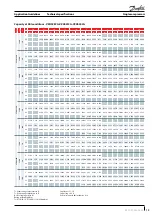


Single compressors
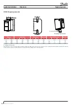
Electrical data, connections and wiring
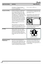
Wiring connections
R
E
LA
Y
1
L1
91
L1
U
96
T1/U
L2
92
L2
V
97
T2/V
L3
93
L3
W
98
T3/W
95
PE
PE
99
45
0/4-20 mA A OUT / DIG OUT
42
0/4-20 mA A OUT / DIG OUT
50
+10 V OUT
NC
53
A IN
NO
02
03
54
A IN
COM
01
55
COM A IN/OUT
NC
06
NO
05
12
+24 V OUT
COM
04
18
DIGI IN
19
DIGI IN
27
DIGI IN
29
DIGI IN
20
COM D IN
N RS-485
69
P RS-485
68
Com RS-485
61
R
E
LA
Y
2
C
D
S8
03
Legends:
A: Analog
DIGI: Digital
IN: Input
OUT: Output
COM: Common
NC: Normally-closed
NO: Normally-open
Open loop
Process loop
91,92,93
3 phases mains input
x
x
95
Earth
x
x
42,45
0/4-20 mA Analague Output or Digital
Output
-
-
50
+10V DC Output
-
-
53
0-10V or 4-20mA Analague Input
x
-
54
0-10V or 4-20mA Analague Input
-
x
55
Com Analague In/Out
x
-
12
+24V output
-
-
18
External On/Off(NO)
x
x
19
Digital Input
-
-
27
Safety Device e.g.: HP/LP switch
x
x
29
Digital Input
-
-
20
Com Digital Input
-
-
98
To Compressor T3
x
x
97
To Compressor T2
x
x
96
To Compressor T1
x
x
99
Earth
x
x
03,02,01
Relay 1
-
-
06,05,04
Relay 2
-
-
69,68
RS485 Bus
-
-
61
RS485 Bus Com
-
-
-: Optional connection
X: Mandatory connection
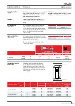
The CDS803 frequency converter is factory
preset with parameters for the open loop control
principle. The process loop control principle can
be selected by changing parameters in the “Quick
menu.”
Open loop: preset on input 53
0 - 10 V control
Frequency converter in slave mode
Process loop: preset on input 54
4 - 20 mA control
Frequency converter under own PID controller
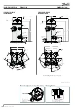
VZH028/035/044 scroll compressors are designed
to operate without any assistance.
Electrical connections
21
FRCC.PC.034.A2.02
Application Guidelines


