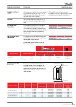


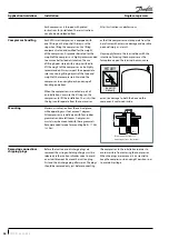
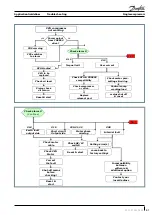
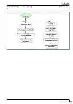
Single compressors
System design recommendations
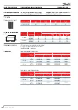
HP
4 m/s or more
0.5% slope
To condenser
max. 4 m
max. 4 m
0.5% slope
U-trap, as short as possible
U-trap
4m/s or more
U trap, as short as possible
Evaporator
LP
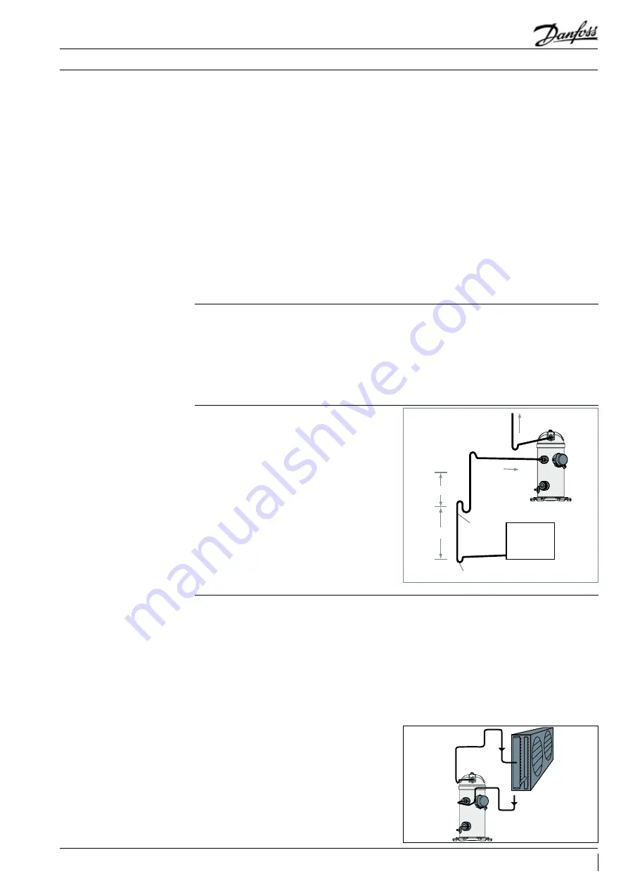
8 to 12 m/s
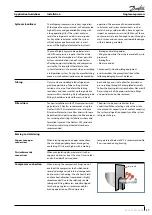
HP
LP
Condenser
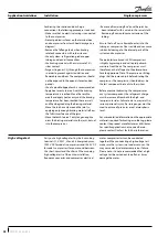
3D flexibility
U Trap
Upper loop
The working pressure in systems with R410A is
about 60% higher than in systems with R22 or
R407C. Consequently, all system components and
piping must be designed for this higher pressure
level.
Proper piping practices should be employed to
ensure adequate oil return, even under minimum
load conditions with special consideration given
to the size and slope of the tubing coming
from the evaporator. Tubing returns from the
evaporator should be designed so as not to trap
oil and to prevent oil and refrigerant migration
back to the compressor during off-cycles.
In systems with R410A, the refrigerant mass
flow will be lower compared to R22/R407C
systems. To maintain acceptable pressure
drops and acceptable minimum gas velocities,
the refrigerant piping must be reduced in size
compared to R22 / R407C systems. Take care
also to not create overly high pressure drops
as in R410A systems the negative impact of
high pressure drops on the system efficiency is
stronger than in R22/R407C systems.
The design in this guideline is for short circuit
application. However, for long circuit and split
system application, an oil separator and an
external non-return valve are recommended for
use based on system qualification status.
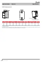
CDS803 frequency converter integrates a special
feature in the compressor functions in order
to improve and secure the oil recovery from
the system. Refer to “Oil Return Management”
section.
When the condenser is mounted at a higher
position than the compressor, a suitably sized
U-shaped trap close to the compressor is
necessary to prevent oil leaving the compressor
from draining back to the discharge side of the
compressor during off cycle. The upper loop also
helps avoid condensed liquid refrigerant from
draining back to the compressor when stopped.
For Inverter applications with long lines we
recommend the use of an oil separator even if it
is only the condenser which is far away from the
unit.
Piping must also be designed with care in order
to make sure the remaining oil not trapped by
the oil separator is properly carried over the
system.
Basic principal is shown here. Note that for the
discharge line, following the same principle
as for the suction line with a U-trap every 4 m
must be applied between discharge U-trap and
upper U-trap where the condenser is above the
compressor unit.
We also recommend installing one check valve
on the discharge line to the condenser next to
the condenser to avoid the possibility of having
the discharge tube full of liquid during off cycles;
discharge lines flooded by liquid which may
create start-up issues by drive over-torque or HP
switch trip.
Piping should be designed with adequate
three-dimensional flexibility. It should not be in
contact with the surrounding structure, unless
a proper tubing mount has been installed.
This protection proves necessary to avoid
excess vibration, which can ultimately result in
connection or tube failure due to fatigue or wear
from abrasion. Aside from tubing and connection
damage, excess vibration may also transmitted
to the surrounding structure and generate an
unacceptable noise level within that structure.
For more information on noise and vibration, see
“Sound and Vibration Management” section.
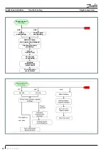
If the evaporator lies above the compressor, as
is often the case in split or remote condenser
systems, the addition of a pump-down cycle
is strongly recommended. If a pump-down
cycle were to be omitted, the suction line must
have a loop at the evaporator outlet to prevent
refrigerant from draining into the compressor
during off-cycles.
If the evaporator were situated below the
compressor, the suction riser must be trapped so
as to prevent liquid refrigerant from collecting at
the outlet of the evaporator while the system is
idle, which would mislead the expansion valve’s
sensor (thermal bulb) at start-up.
Essential piping design
considerations
Suction lines
Discharge lines
29
FRCC.PC.034.A2.02
Application Guidelines