


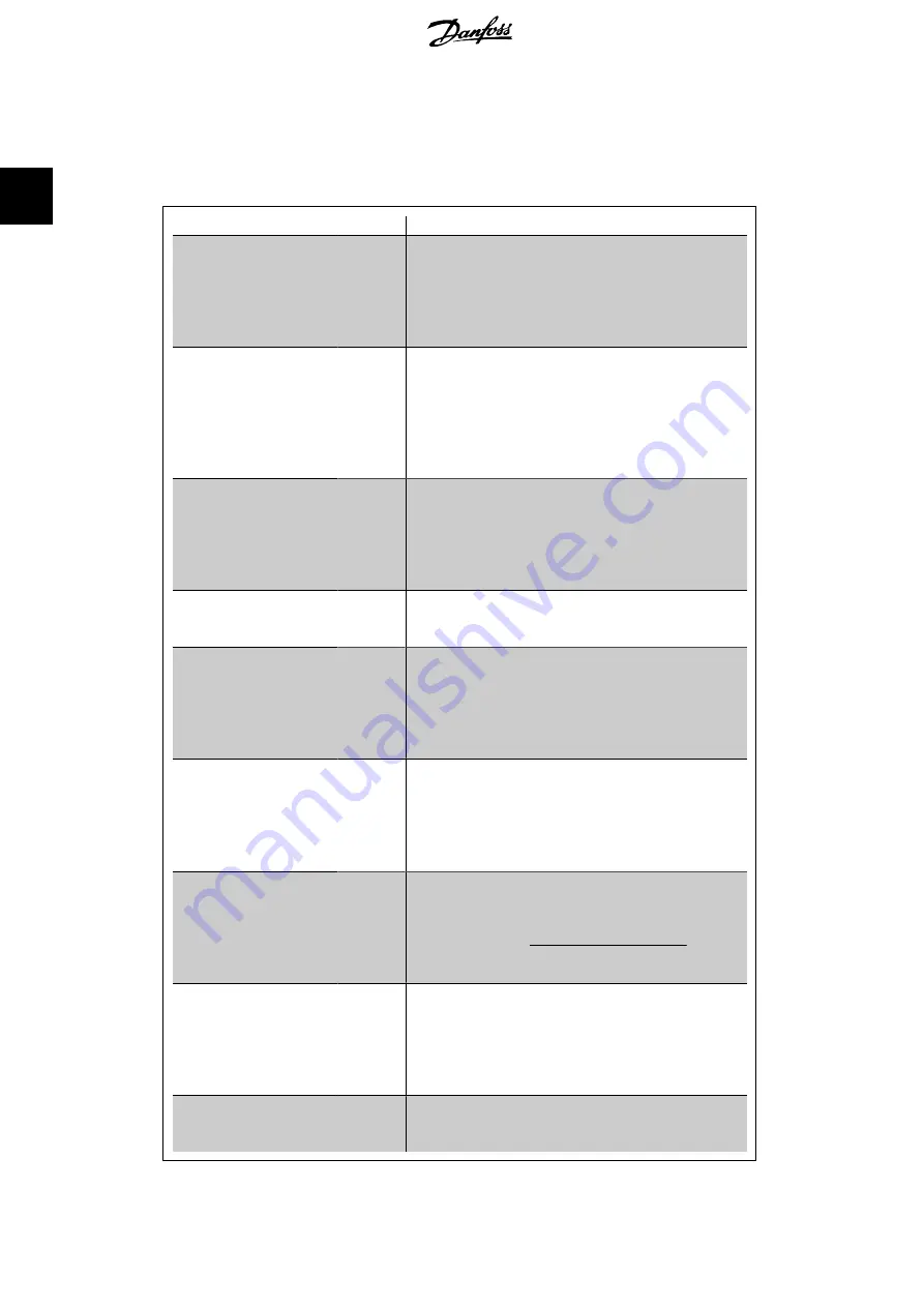
The drive’s Closed Loop Controller is capable
of handling more complex applications, such
as situations where a conversion function is
applied to the feedback signal or situations
where multiple feedback signals and/or set-
point references are used. The below table
summarizes the additional parameters than
may be useful in such applications.
Parameter
Description of function
Feedback 2 Source
Feedback 3 Source
par.
20-03
par.
20-06
Select the source, if any, for Feedback 2 or 3. This is
most commonly a drive analog input, but other sources
are also available. Par. 20-20 determines how multiple
feedback signals will be processed by the drive’s Closed
Loop Controller. By default, these are set to
No func-
tion
[0].
Feedback 1 Conversion
Feedback 2 Conversion
Feedback 3 Conversion
par.
20-01
par.
20-04
par.
20-07
These are used to convert the feedback signal from one
type to another, for example from pressure to flow or
from pressure to temperature (for compressor applica-
tions). If
Pressure to temperature
[2] is selected, the
refrigerant must be specified in par. Group 20-3*,
Feedback Adv. Conv. By default, these are set to
Line-
ar
[0].
Feedback 1 Source Unit
Feedback 2 Source Unit
Feedback 3 Source Unit
par.
20-02
par.
20-05
par.
20-08
Select the unit for a feedback source, prior to any con-
versions. This is used for display purposes only. This
parameter is only available when using
Pressure to
Temperature
feedback conversion.
Feedback Function
par.
20-20
When multiple feedbacks or setpoints are used, this
determines how they will be processed by the drive’s
Closed Loop Controller.
Setpoint 1
Setpoint 2
Setpoint 3
par.
20-21
par.
20-22
par.
20-23
These setpoints can be used to provide a setpoint ref-
erence to the drive’s Closed Loop Controller. Par. 20-20
determines how multiple setpoint references will be
processed. Any other references that are activated in
par. group 3-1* will add to these values.
Refrigerant
par.
20-30
If any Feedback Conversion (par. 20-01, 20-04 or
20-07) is set to
Pressure to Temperature
[2], the re-
frigerant type must be selected here. If the refrigerant
used is not listed here, select
User defined
[7] and
specify the characteristics of the refrigerant in par.
20-31, 20-32 and 20-33.
Custom Refrigerant A1
Custom Refrigerant A2
Custom Refrigerant A3
par.
20-31
par.
20-32
par.
20-33
When par. 20-30 is set to
User defined
[7], these pa-
rameters are used to define the value of coefficients A1,
A2 and A3 in the conversion equation:
Temperature
=
A
2
ln
(
pressure
+ 1)
−
A
1
−
A
3
PID Start Speed [RPM]
PID Start Speed [Hz]
par.
20-82
par.
20-83
The parameter that is visible will depend on the setting
of par. 0-02, Motor Speed Unit. In some applications,
after a start command it is important to quickly ramp
the motor up to some pre-determined speed before ac-
tivating the drive’s Closed Loop Controller. This param-
eter defines that starting speed.
On Reference Bandwidth par.
20-84
This determines how close the feedback must be to the
setpoint reference for the drive to indicate that the
feedback is equal to the setpoint.
2. Introduction to VLT HVAC Drive
VLT
®
HVAC Drive Design Guide
32
MG.11.B2.02 - VLT
®
is a registered Danfoss trademark
2


