


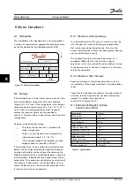


4.5 CleanConnect
®
Connection Diagram
shows the connection power plug for OneGearDrive Hygienic DA09LA10 in Y-connection with thermistors.
130BB868.12
V1
W1
U1
U
V
W
2
3
D
C
A
B
1
4
T1
T2
Figure 4.4 CleanConnect
®
OneGearDrive Connection
Description
Inverter output
Pin
Typical cross-section
Maximum cross-section
Motor winding
U
1
1.5 mm
2
/AWG 16
2.5 mm
2
/AWG 14
V
3
W
4
Protective ground
PE
2
1.5 mm
2
/AWG 16
2.5 mm
2
/AWG 14
Temperature protection
1)
KTY 84-130
T1
A
0.75 mm
2
/AWG 20
1.5 mm
2
/AWG 16
T2
B
Table 4.3 CleanConnect
®
OneGearDrive Connection
1) When connected to VLT
®
AutomationDrive FC 302 and VLT
®
Decentral Drive FCD 302, use analog input terminal 54, KTY sensor 1. For
information about parameter setting and programming, refer to the corresponding instruction manual.
T1
KTY 84-130
VLT
®
AutomationDrive FC 302
1)
VLT
®
Decentral Drive FCD 302
1)
T2
KTY sensor 1
Analog input 54
Table 4.4 Connections T1 and T2
1) Only if connected
4.6 Overload Protection
Take note of the relevant circuit diagram for motors with thermally activated winding protection (see
Avoid automatic resetting after the winding has cooled.
The output of the motors is normally adequately rated. The rated current does not represent a measure of gear unit
utilization in these cases and cannot be used as overload protection for the gear unit. In some cases, the way in which the
machine being driven is loaded can exclude any overloading as a matter of course. In other cases, it is necessary to protect
the gear unit by mechanical means (e.g., slip clutch, sliding hub, etc.). This depends on the maximum permissible limit
torque M
LT
in continuous running duty specified on the nameplate.
Electrical Installation
Instruction Manual
16
Danfoss A/S © 08/2014 All rights reserved.
MG75C422
4
4


