


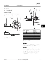


4.4 Cage Clamp Connection Diagram
shows the OneGearDrive DA09LA10 with terminal box in Y-connection and the connection to the thermal
protection.
130BD422.10
V1
W1
U1
U
V
W
PE
U
V
W
T1
T2
Figure 4.3 Cage Clamp Connection Diagram
Description
Inverter output
Color
Typical cross-section
Maximum cross-section
Motor winding
U
Black
1.5 mm
2
/AWG 16
2.5 mm
2
/AWG 14
V
Blue
W
Brown
Protective ground
PE
Yellow/green
1.5 mm
2
/AWG 16
2.5 mm
2
/AWG 14
Temperature protection
1)
KTY 84-130
T1
White
0.75 mm
2
/AWG 20
1.5 mm
2
/AWG 16
T2
Brown
Table 4.1 Cage Clamp Connections
1) When connected to VLT
®
AutomationDrive FC 302 and VLT
®
Decentral Drive FCD 302, use analog input terminal 54, KTY sensor 1. For
information about parameter setting and programming, refer to the corresponding instruction manual.
T1
KTY 84-130
VLT
®
AutomationDrive FC 302
1)
VLT
®
Decentral Drive FCD 302
1)
T2
KTY sensor 1
Analog input 54
Table 4.2 Connections T1 and T2
1) Only if connected
NOTICE!
After connection, tighten all four screws on the terminal box cover. The tightening torque is 3 Nm.
Electrical Installation
Instruction Manual
MG75C422
Danfoss A/S © 08/2014 All rights reserved.
15
4
4


