


6.1.1.1 Figure
1
2
4
3
5
6
7
8
9
10
130BC429.11
11
1
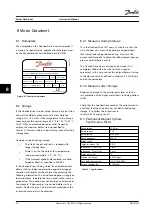
Rotor width, minimum 0.217 in [5.5 mm]
2
Air gap, maximum 0.018 in [0.45 mm]
3
Fastening screws
4
Armature plate
5
Magnet
6
Springs
7
Hub for rotor
8
Rotor
9
Friction plate
10
Hollow screws
11
Brake cover and nuts
Figure 6.1 Brake and Rotor
1.
Open the brake completely by turning the brake
cover nuts (11) counter-clockwise.
2.
Loosen the fastening screws (3) completely by
turning them counter-clockwise.
3.
Remove the installed brake and rotor from the
hub of the rotor (7).
4.
Assemble the new brake and rotor on the hub of
the rotor (7).
5.
Tighten the fastening screws (3).
6.
Close the brake cover and tighten the covering
nuts (11).
NOTICE!
After the rotor has been exchanged, the complete
braking torque will only be effective after the brake
linings at the rotor have been run in.
Check the brake cover seal before closing it and
exchange the seal if any damage is detected.
6.1.2 Adjusting the Nominal Brake Torque
and Replacing the Springs
The nominal brake torque can be adjusted and broken
springs can be replaced. Follow the instructions in
chapter 6.1.1 Replacing the Brake and Rotor
to open the
brake as reference for the nominal brake torque:
Nominal brake torque [Nm]
Number of springs
10
7
7
5
6
4
4
3
Table 6.2 Nominal Brake Torque
Maintenance, Diagnostics an...
Instruction Manual
MG75C422
Danfoss A/S © 08/2014 All rights reserved.
19
6
6


