


4.3 Parameter Group 2: Brakes
4.3.1 2-** Brakes
4.3.2 2-0* DC-Brake
The purpose of DC-brake function is to brake a rotating
motor by applying DC-current to the motor.
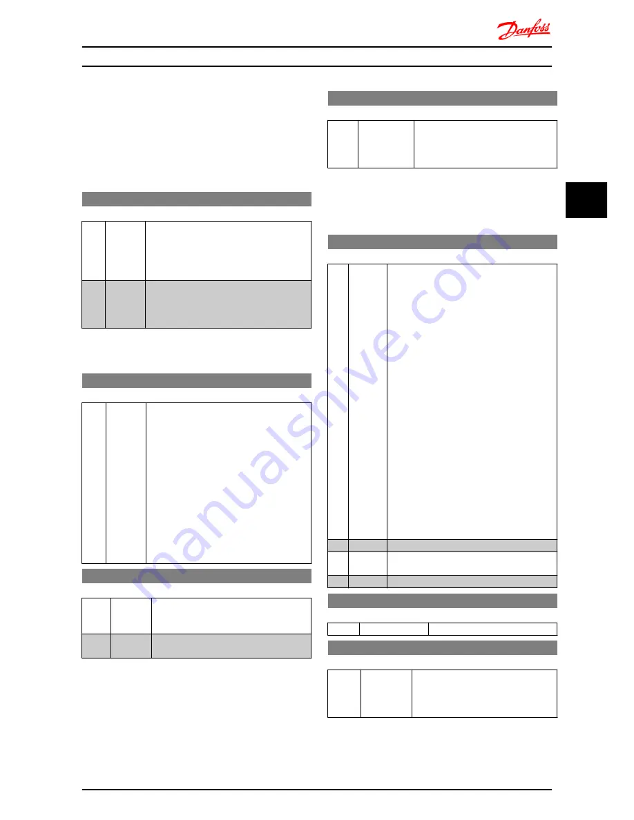
2-00 DC Hold Current
Range:
Function:
This parameter either holds the motor (holding
torque) or pre-heats the motor.
The parameter is active if
DC Hold
has been
selected in either
1-72 Start Function
or
1-80
Function at Stop
.
50%
*
[0-100%] Enter a value for holding current as a
percentage of the rated motor current set in
1-24 Motor Current
. 100% DC holding current
corresponds to I
M,N
.
NOTE
Avoid 100% current too long as it may overheat the motor.
2-01 DC Brake Current
Range:
Function:
50
%
*
[0-150%] Set DC-current needed to brake rotating
motor.
Activate DC-brake in one of the four following
ways:
1.
DC-brake command, see
5-1* Digital
Inputs
choice [5]
2.
DC Cut-in function, see
2-04 DC-Brake
Cut-in Speed
3.
DC-brake selected as start function,
see
1-72 Start Function
4.
DC-brake in connection with
Flying
Start
,
1-73 Flying Start
.
2-02 DC-Braking Time
Range:
Function:
DC-braking time defines the period during
which
DC-brake current
is applied to the
motor.
10.0 s
*
[0.0-60 s] Set the time DC-braking current, set in
2-01
DC Brake Current
, must be applied.
NOTE
If DC-brake is activated as start function, DC-brake time is
defined by
start delay time
.
2-04 DC-Brake Cut-in Speed
Range:
Function:
0.0 Hz
*
[0.0-400.0 Hz] Set DC-brake cut-in speed to activate
DC braking current, set in
2-01 DC Brake
Current
, when ramping down.
When set to 0 the function is off.
4.3.3 2-1* Brake Energy Function
Use the parameters in this group for selecting dynamic
braking parameters.
2-10 Brake Function
Option:
Function:
Resistor Brake:
The resistor brake limits voltage in the
intermediate circuit when the motor acts as
generator. Without brake resistor, the frequency
converter eventually trips.
The resistor brake consumes surplus energy
resulting from motor braking. A frequency
converter with brake, stops a motor faster than
without a brake, which is used in many
applications. Requires connection of external
brake resistor.
An alternative to the resistor brake is the AC
brake.
NOTE
Resistor brake is only functional in
frequency converters with integrated
dynamic brake. An external resistor must
be connected.
AC Brake:
The AC brake consumes surplus energy by
creating power loss in the motor.
It is important to keep in mind that an increase
in power loss causes motor temperature to rise.
[0]
*
Off
No brake function.
[1]
Resistor
Brake
Resistor brake is active.
[2]
AC Brake AC brake is active.
2-11 Brake Resistor (Ohm)
Range:
Function:
5 Ω
*
[5-5000 Ω]
Set brake resistor value.
2-16 AC Brake, Max Current
Range:
Function:
100.0%
*
[0.0-150.0%] Enter max. permissible current for AC-
braking to avoid overheating of motor.
100% equals motor current set in
1-24
Motor Current
.
Parameter Descriptions
VLT
®
Micro Drive FC 51 Programming Guide
MG02C602 - VLT
®
is a registered Danfoss trademark
19
4
4


