CTW
REF
CTW
REF
PCD 2
write
PCD 3
write
STW
MAV
STW
MAV
PCD 2
read
PCD 3
read
Instance
100
101
150
151
Originator (PLC) --> Target (Drive)
Fixed contents
User defined contents
Instance
STW
MAV
70
STW
MAV
71
CTW
REF
20
CTW
REF
21
Byte #
Byte #
Word #
Word #
Target (Drive) --> Originator (PLC)
1 2 3 4 5 6 7 8
1 2 3 4 5 6 7 8
1 2 3 4
1 2 3 4
130BE709.10
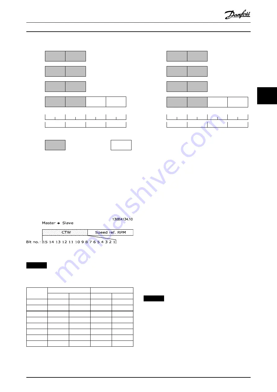
Illustration 4.3 Process Data
4.4 ODVA Control Profile
4.4.1 Control Word under Instances 20/70
and 21/71
Set
parameter 8-10 Control Word Profile
to ODVA and select
the instance in
parameter 10-10 Process Data Type Selection
.
Illustration 4.4 The Control Word in Instances 20 and 21
NOTICE
The bits 00 and 02 in instance 20 are identical with bits
00 and 02 in the more extensive instance 21.
Bit
Instance 20
Instance 21
Bit = 0
Bit = 1
Bit = 0
Bit = 1
00
Stop
Run Fwd
Stop
Run Fwd
01
–
–
Stop
Run Rev
02
No function Fault reset
No function Fault reset
03
–
–
–
–
04
–
–
–
–
05
–
–
–
Net Ctrl
06
–
–
–
Net Ref
07–15
–
–
–
–
Table 4.2 Bits in Instances 20 and 21
Explanation of the bits:
Bit 0, Run Fwd
Bit 0 = 0: The frequency converter has a stop command.
Bit 0 = 1: Leads to a start command, and the frequency
converter runs the motor clockwise.
Bit 1, Run Rev
Bit 1 = 0: Leads to a stop of the motor.
Bit 1 = 1: Leads to a start reverse of the motor, and the
frequency converter runs the motor counterclockwise.
Bit 2, Fault Reset
Bit 2 = 0: There is no reset of a trip.
Bit 2 = 1: A trip is reset.
Bit 3, No function
Bit 3: No function.
Bit 4, No function
Bit 4: No function.
Bit 5, Net Control
Bit 5 = 0: The frequency converter is controlled via the
standard inputs.
Bit 5 = 1: The DeviceNet controls the frequency converter.
NOTICE
Changes affect
parameter 8-50 Coasting Select
to
parameter 8-56 Preset Reference Select
.
Bit 6, Net Reference
Bit 6 = 0: Reference is from the standard inputs.
Bit 6 = 1: Reference is from DeviceNet.
Control
Programming Guide
MG92F102
Danfoss A/S © 12/2015 All rights reserved.
11
4
4


