


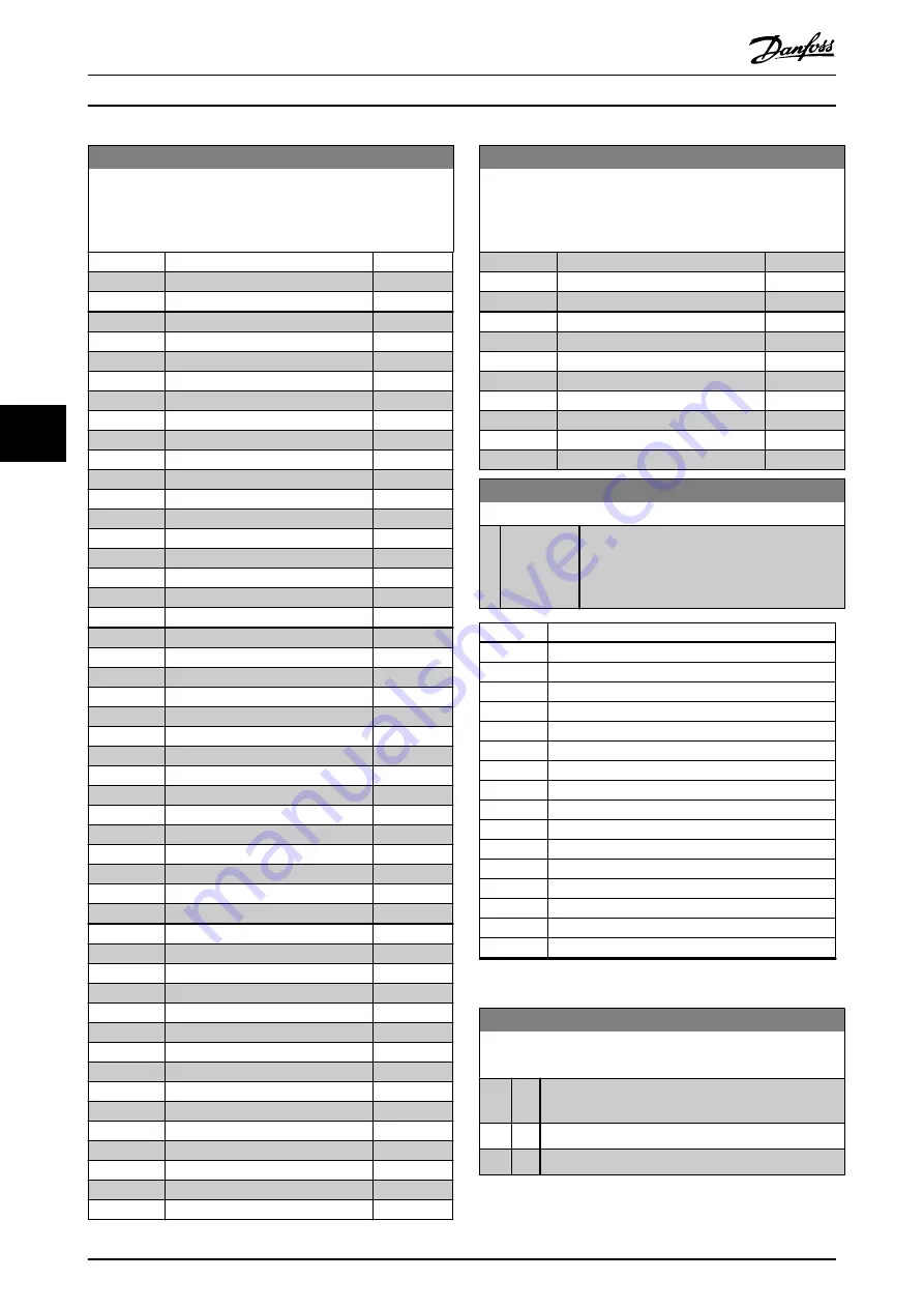
10-12 Process Data Config Read
Select the process read data for I/O assembly instances 101/151.
Elements [2] and [3] of this array can be selected. Elements [0]
and [1] of the array are fixed.
Option:
Function:
[1670]
Pulse Output #29 [Hz]
[1671]
Relay Output [bin]
[1672]
Counter A
[1673]
Counter B
[1674]
Prec. Stop Counter
[1675]
Analog In X30/11
[1676]
Analog In X30/12
[1677]
Analog Out X30/8 [mA]
[1678]
Analog Out X45/1 [mA]
[1679]
Analog Out X45/3 [mA]
[1684]
Comm. Option STW
[1687]
Bus Readout Alarm/Warning
[1689]
Configurable Alarm/Warning Word
[1690]
Alarm Word
[1691]
Alarm Word 2
[1692]
Warning Word
[1693]
Warning Word 2
[1694]
Ext. Status Word
[1836]
Analog Input X48/2 [mA]
[1837]
Temp. Input X48/4
[1838]
Temp. Input X48/7
[1839]
Temp. Input X48/10
[1843]
Analog Out X49/7
[1844]
Analog Out X49/9
[1845]
Analog Out X49/11
[1860]
Digital Input 2
[3421]
PCD 1 Read from MCO
[3422]
PCD 2 Read from MCO
[3423]
PCD 3 Read from MCO
[3424]
PCD 4 Read from MCO
[3425]
PCD 5 Read from MCO
[3426]
PCD 6 Read from MCO
[3427]
PCD 7 Read from MCO
[3428]
PCD 8 Read from MCO
[3429]
PCD 9 Read from MCO
[3430]
PCD 10 Read from MCO
[3440]
Digital Inputs
[3441]
Digital Outputs
[3450]
Actual Position
[3451]
Commanded Position
[3452]
Actual Master Position
[3453]
Slave Index Position
[3454]
Master Index Position
[3455]
Curve Position
[3456]
Track Error
[3457]
Synchronizing Error
[3458]
Actual Velocity
[3459]
Actual Master Velocity
[3460]
Synchronizing Status
10-12 Process Data Config Read
Select the process read data for I/O assembly instances 101/151.
Elements [2] and [3] of this array can be selected. Elements [0]
and [1] of the array are fixed.
Option:
Function:
[3461]
Axis Status
[3462]
Program Status
[3464]
MCO 302 Status
[3465]
MCO 302 Control
[3470]
MCO Alarm Word 1
[3471]
MCO Alarm Word 2
[4280]
Safe Option Status
[4282]
Safe Control Word
[4283]
Safe Status Word
[4285]
Active Safe Func.
[4287]
Time Until Manual Test
10-13 Warning Parameter
Range:
Function:
0
*
[0 - 65535 ] View a DeviceNet-specific warning word. One
bit is assigned to every warning. Refer to the
VLT
®
MCA 104 DeviceNet Installation Guide
for
further information.
Bit
Description
0
Bus not active.
1
Explicit connection timeout.
2
I/O connection.
3
Retry limit reached.
4
Actual is not updated.
5
CAN bus off.
6
I/O send error.
7
Initialization error.
8
No bus supply.
9
Bus off.
10
Error passive.
11
Error warning.
12
Duplicate MAC ID error.
13
RX queue overrun.
14
TX queue overrun.
15
CAN overrun.
Table 6.1 Warning Bits
10-14 Net Reference
Read only from LCP.
Option: Function:
Select the reference source in instances 21/71 and
20/70.
[0]
*
Off Enables reference via analog/digital inputs.
[1]
On Enables reference via the fieldbus.
Parameters
VLT
®
DeviceNet MCA 104
34
Danfoss A/S © 12/2015 All rights reserved.
MG92F102
6
6


