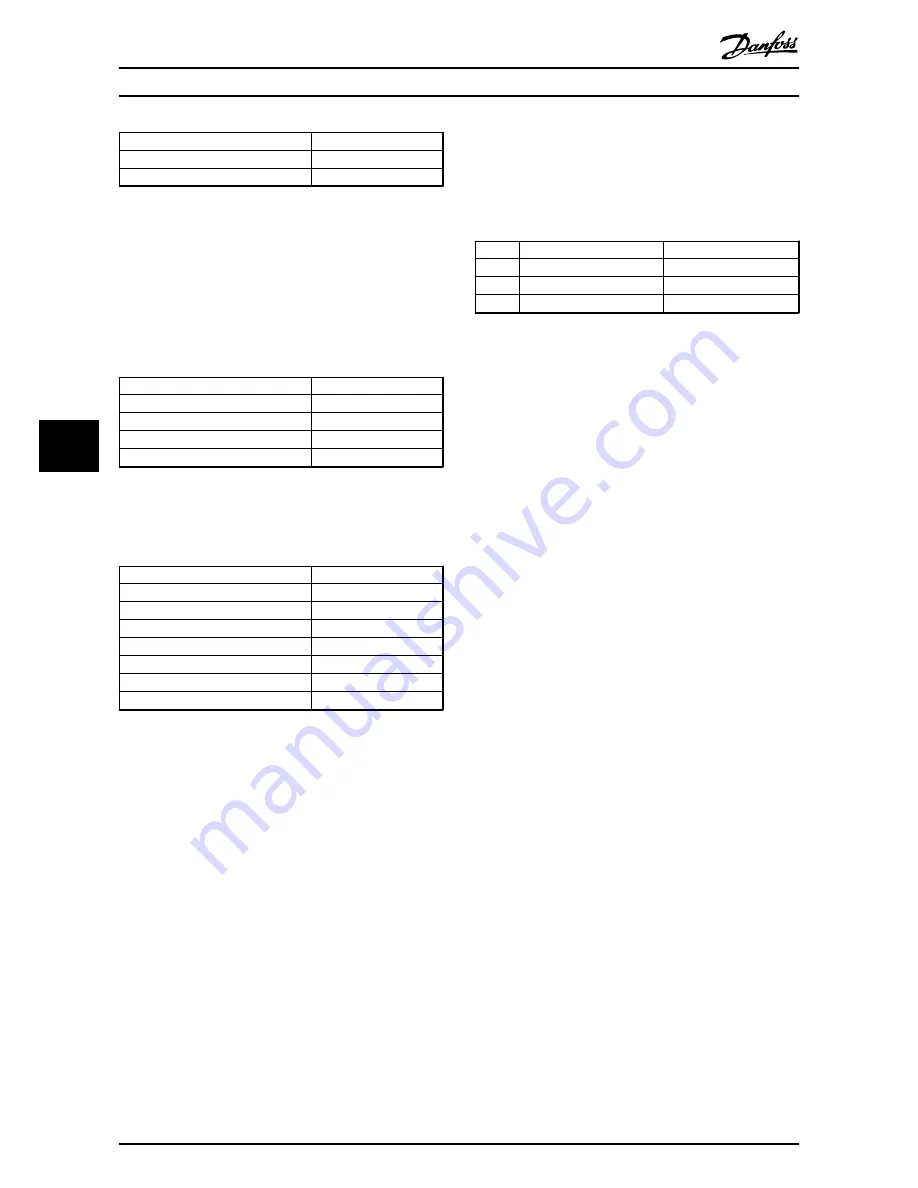
background image

27-7* Connections

Example

27-70.0 Relay 1

[1] Drive 2 Enable

27-70.1 Relay 2

[2] Drive 3 Enable

Table 6.7 Master Drive Settings, 27-7* Connections

6.1.3 Follower Drive Settings

Follower drives must be configured for open loop
operation with basic settings as described in 

6.1.1 Basic

Settings

.

Configure only one of the followers and to copy the
settings by using the LCP.

Open Loop Settings (Follower)

Example/Remarks

1-00 Configuration Mode

[0] Open Loop

3-02 Minimum Reference

0

3-03 Maximum Reference

50 (Hz)

3-15 Reference 1 Source

[7] Pulse Input 29

Table 6.8 Open Loop Settings (Follower)

The terminal 29 is used as a pulse input for the reference
signal and must be scaled.

5-** Digital In/Out (Follower)

Example/Remarks

5-02 Terminal 29 Mode

[0] Input

5-13 Terminal 29 Digital Input

[32] Pulse Input

5-50 Terminal 29 Low Frequency

0 (Hz)

5-51 Terminal 29 High Frequency

5000 (Hz)

5-52 Term. 29 Low Ref. Value

0

5-53 Term. 29 High Ref. Value

50 (Hz)

5-10 Terminal 18 Digital Input

Start

Table 6.9 5-** Digital In/Out (Follower)

6.1.4 Sleep Mode

The following describes how to configure the frequency
converter for de-staging the last variable speed pump in
applications with more than one frequency converter.

The necessary steps for the configuration are:

1.

Set parameter 27-34.01 higher than the minimum
speed in 

4-11 Motor Speed Low Limit [RPM]

/

4-12 Motor Speed Low Limit [Hz]

 to enable sleep

function (setting it to zero will disable the
function).

2.

Set 

27-21 Override Limit

 to wake up the

application.

After wake up the pump with the least running hours
starts.

NOTICE

If the master drive does not wake up properly, the
frequency converter is not able to reach its de-staging
speed and the delays in parameter group 27-** have to
be adjusted.


Stage ON [Hz]

Stage OFF [Hz]

Stage 1 48.5 (i.e. parameter 2732.1) 30 (i.e. parameter 2734.1)
Stage 2 48.5 (i.e. parameter 2732.2) 40 (i.e. parameter 2734.2)
Stage 3 - (i.e. parameter 2732.3)

42 (i.e. parameter 2734.3)

Table 6.10 Example Settings for 27-3*, 3 Pumps with
Sleep Mode Enabled

“Stage X” refers to the stage the cascade is
running in (stage 1 

 cascade is running in stage

1, only 1 pump is running)

Pumps 2 and 3 are started on 48.5 Hz

Pump 3 is stopped on 42 Hz, Pump 2 is stopped
on 40 Hz and Pump 1 is stopped on 30 Hz

It might be necessary to fine adjust the stage
on/off speeds to optimise the energy
consumption, if not auto tuned. It is
recommended to use Auto Tune Staging Speeds
by enabling the feature in 

27-30 Auto Tune

Staging Speeds

.

NOTICE

Parameter 2732.3 is irrelevant in this case, because there
is nothing left to stage on in stage 3.

Configuration Examples

VLT

®

 AQUA Drive MCO 101/MCO 102

42

MI38C402 - VLT

®

 is a registered Danfoss trademark

6

6

Summary of Contents for vlt aqua

Page 1: ...MAKING MODERN LIVING POSSIBLE V VLTp AQUA Drive Cascade Controller Options MCO 101 102 Operating Instructions...

Page 2: ...arge before performing any service or repair work The amount of wait time is listed in the Discharge Time table Failure to wait the specified time after power has been removed before doing service or...

Page 3: ...Safety VLT AQUA Drive MCO 101 MCO 102 MI38C402 VLT is a registered Danfoss trademark...

Page 4: ...1 Before Start 12 3 1 2 Extended Cascade Controller MCO 101 12 3 1 3 Advanced Cascade Controller MCO 102 14 4 Configuring the System 16 4 1 Configuring the Extended and Advanced Cascade Controller 16...

Page 5: ...ttings 27 2 26 5 1 6 Staging Speed 27 3 28 5 1 7 Staging Settings 27 4 29 5 1 8 Alternation Settings 27 5 30 5 1 9 Digital Inputs 27 6 31 5 1 10 Connections 27 7 35 5 1 11 Readouts 27 9 36 5 2 Paramet...

Page 6: ...For further information see 2 Application Types The Extended Cascade Controller can be used in two different modes with the extended features controlled by parameter group 27 to extend the number of a...

Page 7: ...Instructions provide details on installation and operation of the frequency converter The VLT AutomationDrive FC 302 Programming Guide provides greater detail on working with parameters and many appl...

Page 8: ...connected pumps and frequency converters to the master The necessary hardware is explained in the following hardware configuration examples 2 2 1 Extension of Basic Cascade Parameter Group 25 Control...

Page 9: ...able speed pump In this configuration the VLT AQUA Drive controls one variable speed pump and up to 8 fixed speed pumps The fixed speed pumps are staged and de staged as needed through contactors dire...

Page 10: ...ges the pumps on and off according to system requirements Compared to traditional cascade control the number of running pumps is controlled by speed instead of feedback To obtain the highest energy sa...

Page 11: ...f the benefits of the master follower configuration with some of the initial cost savings of the fixed speed configuration It is a good choice when the extra capacity of the fixed pumps is rarely need...

Page 12: ...0 100 100 100 200 200 C 1 100 200 300 400 2 3 4 130BD073 10 Illustration 2 7 Valid Configuration Example NOTICE Invalid configurations like in Illustration 2 8 will still run but will not stage on all...

Page 13: ...70 0 RELAY 1 8 Pump 1 to Drive 1 27 70 1 RELAY 2 16 Pump 2 to Drive 1 27 70 9 RELAY 10 74 Pump 3 to Mains 27 70 10 RELAY 11 75 Pump 4 to Mains 27 70 11 RELAY 12 76 Pump 5 to Mains 2 2 4 Using Soft Sta...

Page 14: ...last drive running after de staging This is achieved by giving the connected pump the highest priority in the parameters for runtime balancing e g by programming the drive with the MCO 101 or the MCO...

Page 15: ...590 Hz the difference from standard software is that it cannot be flashed i e neither downgraded nor upgraded 3 1 2 Extended Cascade Controller MCO 101 The MCO 101 option includes 3 pieces of change o...

Page 16: ...ow voltage parts and PELV systems see Illustration 3 4 1 1 1 1 10 2 3 4 5 6 7 8 9 12 11 2 2 3 1 1 1 1 10 2 3 4 5 6 7 8 9 12 11 3 3 3 1 1 1 1 10 2 3 4 5 6 7 8 9 12 11 2 2 2 130BA176 11 Illustration 3 4...

Page 17: ...g kit depending on the enclosure Type Description Ordering number Options MCF 105 Mounting Kit frame size A2 and A3 40 mm for one C Option 130B7530 MCF 105 Mounting Kit Frame size A5 130B7532 MCF 105...

Page 18: ...d relief the cables by the enclosed cable strips 6 Fit the extended cradle and terminal cover 7 Remount the LCP 8 Connect power to the frequency converter Wiring the Terminals 130BB025 11 Illustration...

Page 19: ...should equally balance the running hours between the pumps then use the default values 27 17 Motor Starters All fixed speed pumps must be the same 27 18 Spin time for unused pumps Depends on the size...

Page 20: ...ed the system pressure is still maintained but the pumps are beginning to operate below their peak efficiency points De staging a pump will cause the speed of the frequency converters to increase into...

Page 21: ...arameter group 27 0 Control Status to check on the status of the Cascade Controller and to control individual pumps Select a specific pump to view the current status the current running hours and the...

Page 22: ...Pumps If a pump is only needed occasionally the Cascade Controller balances the running hours of the pumps through alternation If a pump is not used in 72 hours a pump spin is triggered The spin time...

Page 23: ...in 27 24 Destaging Delay If the system demand continues to drop the system will enter sleep mode 4 2 8 Override Staging De staging Normal staging and de staging handles most of the situations in typi...

Page 24: ...tion of the theoretical curve results in step wise adjusted set points following this curve Set point 1 is the minimum pressure required when the system is running with only one pump operating and und...

Page 25: ...on Select the reference input to be used for the first reference signal 3 15 Reference 1 Source Option Function 3 15 Reference 1 Source 3 16 Reference 2 Source and 3 17 Reference 3 Source define up to...

Page 26: ...Digital Output Option Function 0 No operation 1 Control ready 2 Drive ready 3 Drive rdy rem ctrl 4 Stand by no warning 5 Running 6 Running no warning 8 Run on ref no warn 9 Alarm 5 30 Terminal 27 Digi...

Page 27: ...gital Input applicable value 5 52 Term 29 Low Ref Feedb Value Range Function This parameter is available for FC 302 only 5 53 Term 29 High Ref Feedb Value Range Function 100 999999 999 999999 999 Ente...

Page 28: ...tatus is a readout parameter showing the status of each pump in the system Option Function 6 Offline Fault The pump is not available for use by the Cascade Controller and the pump is connected to main...

Page 29: ...speed pumps All fixed speed pumps must be configured the same Possible choices are 0 Direct Online 1 Soft Starter Adds a delay when staging and de staging corresponding to the soft starter ramp time s...

Page 30: ...cations the override limit is used as wake up condition See 6 1 Master Follower for further information Setpoint SBW 27 70 OBW 27 71 SBW 27 70 OBW 27 71 Actual head OBW timer 27 25 130BA370 11 Illustr...

Page 31: ...he lead pump must be running at minimum speed while the system feedback is still inside the normal operating band before a pump will be turned off to save energy Energy savings may be 27 27 Min Speed...

Page 32: ...Delay and more than one variable speed pump is on a variable speed pump will be turned off 5 1 7 Staging Settings 27 4 Parameters for configuring staging transitions 27 40 Auto Tune Staging Settings...

Page 33: ...tically calculated values If 27 43 Staging Threshold and 27 44 Destaging 27 44 Destaging Threshold Range Function Threshold are modified from the bus or LCP then the new values will be used but will c...

Page 34: ...e when the pump is running below a speed where interruption in operation will not affect the process This minimizes the system disturbance caused by alternations The value is entered as a of the capac...

Page 35: ...85 Latched Pump Derag 120 Lead Pump Start 27 61 Terminal X66 3 Digital Input Option Function 121 Lead Pump Alternation 130 Pump 1 Interlock 131 Pump 2 Interlock 132 Pump 3 Interlock 133 Pump 4 Interl...

Page 36: ...21 Lead Pump Alternation 130 Pump 1 Interlock 27 63 Terminal X66 7 Digital Input Option Function 131 Pump 2 Interlock 132 Pump 3 Interlock 133 Pump 4 Interlock 134 Pump 5 Interlock 135 Pump 6 Interloc...

Page 37: ...ock 131 Pump 2 Interlock 132 Pump 3 Interlock 27 65 Terminal X66 11 Digital Input Option Function 133 Pump 4 Interlock 134 Pump 5 Interlock 135 Pump 6 Interlock 136 Pump 7 Interlock 137 Pump 8 Interlo...

Page 38: ...Pump 3 to Drive 2 27 70 Relay 27 70 Relay is an array parameter used to setup the function of the option relays Depending on which option is installed only the available relays will be visible If Exte...

Page 39: ...ence is a readout parameter that shows the reference output for use with follower drives This reference is available even when the master drive is stopped This is the speed that the frequency converte...

Page 40: ...t ups TRUE 0 Uint1 6 25 26 Destage At No Flow 0 Disabled All set ups TRUE Uint8 Par No Parameter description Default value 4 set up Chan ge duri ng oper ation Con ver sion ind ex Type 25 27 Stage Func...

Page 41: ...Alternation 0 N A All set ups TRUE 0 Uint8 Table 5 1 5 2 2 27 Cascade CTL Option Par No Parameter description Default value 4 set up Chan ge duri ng oper atio n Con ver sion ind ex Type 27 0 Control S...

Page 42: ...mp Up Delay 2 0 s All set ups TRUE 1 Uint1 6 Par No Parameter description Default value 4 set up Chan ge duri ng oper atio n Con ver sion ind ex Type 27 43 Staging Threshold Expres sionLimit All set u...

Page 43: ...erminal X66 13 Digital Input 0 No operation All set ups TRUE Uint8 27 7 Connections Par No Parameter description Default value 4 set up Chan ge duri ng oper atio n Con ver sion ind ex Type 27 70 Relay...

Page 44: ...e 1 1 Small 1601 Reference 0 21 Display Line 1 2 Small 1652 Feedback 0 22 Display Line 1 3 Small 1614 Motor current 0 23 Display Line 2 Large 1613 Frequency 0 24 Display Line 3 Large 2794 Cascade Syst...

Page 45: ...are 1 Set parameter 27 34 01 higher than the minimum speed in 4 11 Motor Speed Low Limit RPM 4 12 Motor Speed Low Limit Hz to enable sleep function setting it to zero will disable the function 2 Set 2...

Page 46: ...ime Hours 19 M Manual Pump Control 18 Master Drive 4 Master Follower Configuration 7 Min Speed De stage Delay 27 27 28 Mixed Pump Configuration 9 8 Pump Selection 16 Multiple Drives 19 N Number Of Fre...

Page 47: ...Supported Configurations 5 Symbols iii U Unequal Size Pump Configuration 8 V Variable Speed Pumps 4 Index VLT AQUA Drive MCO 101 MCO 102 44 MI38C402 VLT is a registered Danfoss trademark...

Page 48: ...Index VLT AQUA Drive MCO 101 MCO 102 MI38C402 VLT is a registered Danfoss trademark 45...

Page 49: ...www danfoss com drives MI38C402 130R0345 MI38C402 Rev 2012 08 21...

Reviews: