67 of 165
M-SV-VT-001-EN Rev. A
Compressor Components
Stator Cooling Temperature Sensor Resistance Verification
There is a Stator Cooling Temperature Sensor located in the rear of the Compressor. It is mounted to
the Radial Bearing Assembly. This sensor contains a single circuit. Refer to Figure 160 (Stator Cooling
Temperature Sensor) for details on the exact location of this sensor.
1. Isolate the Compressor power as described in the
“Electrical Isolation of the Compressor/VFD”
section of this manual.
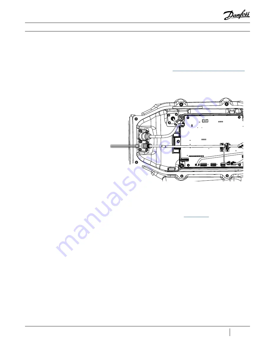
2. Disconnect the external bearing sensor cable from the feed through. Refer to Figure 61 (Rear
Bearing Sensor Feed Through) for details on the location.
Figure 61 - Rear Bearing
Sensor Feed Through
Rear Bearing Sensor
Feed Through
3. Use a multimeter set to resistance, verify the resistance of the circuit at the feed through.
Resistance should be measured between Pins 10 and 11and the measured value should be
within
±
10% of the resistance values listed in the chart in Table 20 (Stator Thermistor R/T Curve
)
.
4. If the value is out of tolerance, the sensor will need to be tested internally. If the sensor is still not
within tolerance, it will need to be replaced. Refer to the
section for details on
how to access the internal Rear Bearing Sensor connector.
5. Restore power to the Compressor.
Summary of Contents for Turbocor VTT Series
Page 2: ...THIS PAGE INTENTIONALLY LEFT BLANK ...
Page 12: ...12 of 165 M SV VT 001 EN Rev A THIS PAGE INTENTIONALLY LEFT BLANK ...
Page 18: ...18 of 165 M SV VT 001 EN Rev A THIS PAGE INTENTIONALLY LEFT BLANK ...
Page 24: ...24 of 165 M SV VT 001 EN Rev A THIS PAGE INTENTIONALLY LEFT BLANK ...
Page 132: ...132 of 165 M SV VT 001 EN Rev A THIS PAGE INTENTIONALLY LEFT BLANK ...
Page 152: ...152 of 165 M SV VT 001 EN Rev A THIS PAGE INTENTIONALLY LEFT BLANK ...
Page 158: ...158 of 165 M SV VT 001 EN Rev A THIS PAGE INTENTIONALLY LEFT BLANK ...
Page 160: ...160 of 165 M SV VT 001 EN Rev A THIS PAGE INTENTIONALLY LEFT BLANK ...


