27
Operation
TFX INSTALLATION AND OPERATION MANUAL
6046279-001 March 2020
5.2.3.4 Jobs
Every time a CAN message is received, jobs are performed
after mapping and before logging.
In the J
OB S
tab, configure the calculation operations you
need for your job.
For the example configuration, you need two jobs with
the function C
AL CULATE
P
ARAMETER
V
ALUE
F
UN CTION
. With this
function, you perform calculation operations and overwrite
interface variables with calculated values.
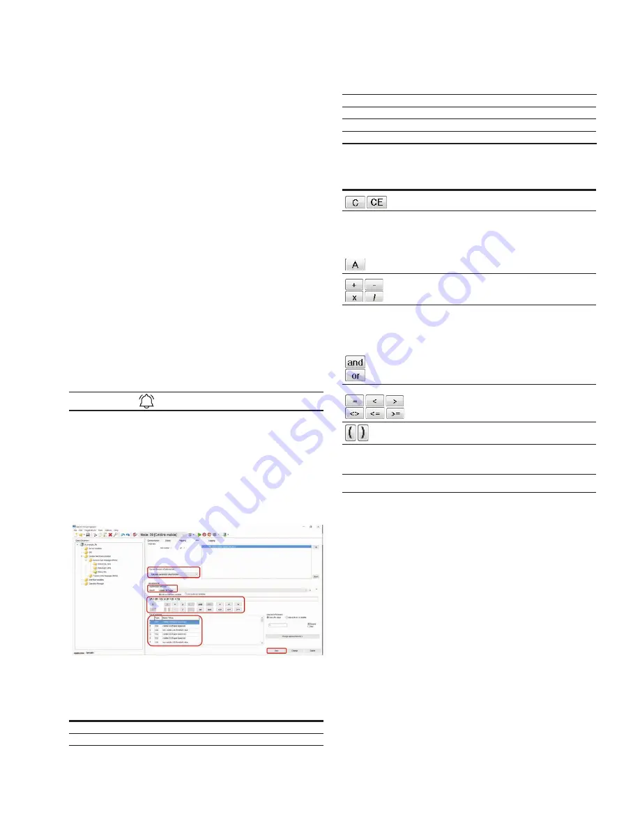
JOB 1
With the first job, you check whether the current speed is
above or below the threshold value. If one of these two
cases applies, the V
OLATILE
U8 T
RIGGER
variable should be set
to the value 1. This triggers logging of the CAN message.
1. Select the J
OB S
tab.
2. In the C
URRENT
FUN CTION
OF
SELE CTE D
J
OB
list, select the
function C
AL CULATE
P
ARAMETER
V
ALUE
F
UN CTION
.
3. In the R
ESULT
list, select the trigger
VOLATILE
U 8 T
RIGGER
.
4. Using the buttons in the
M
ATHEMATI CS
AN D
LOGI C
area,
enter the calculation operations (A < (B – C)) or (D >
(E + F)).
5. Click on button A.
INFORMATION
If you click on a placeholder (e.g. A), this opens the window
I
NPUT
O
PERAN D
I
NFORMATION
OR
OPEN
A
NEW
OPERATION
.
You can find the allocation of the variables for this example
in the table below.
6. Click on the variable in the list that you want to
allocate the placeholder to.
7. Click on the
NEW
button when you have entered the
calculation operations completely.
Allocate the following variables to the placeholders:
Table 26: Variables – Job 1
Variable
Type
Name/value
A
S32
volatile S32 engine speed new
B
S32
volatile S32 engine speed old
C
U16
non-volatile U16 threshold value
D
S32
volatile S32 engine speed new
E
S32
volatile S32 engine speed old
F
U16
non-volatile U16 threshold value
The buttons for entering the calculation operations have the
following functions:
Buttons
Description
C = clear: deletes the entire calculation operation
CE = clear entry: only deletes the last symbol entered
Add variables to the calculation operation.
Click on the button to open a window. Assign fixed
values, interface variables, or device variables to the
variables. After you have defined a variable, the display
on the button jumps to the next variable.
The selected variables are listed under
L
IST
OF
O
PERAN DS
, including their values and types.
Basic calculation types (addition, subtraction,
multiplication, division)
and = logical AND link
If all linked operands are true or not equal to zero, the
result is operation 1. otherwise, the result is operation 0.
or = logical OR link
If one of the linked operands is true or not equal to
zero, the result is operation 1. otherwise, the result is
operation 0.
If both linked variables are full-number values (integers),
the link is made by bits.
Comparison signs (equal to, smaller than, greater than,
not equal to, smaller or equal to, and larger or equal to)
The result is 1 when the comparison is true.
The result is 0 when the comparison is not true.
Brackets
Buttons for calculation operations
NOTICE
The calculation formulas are evaluated from left to right.
Mathematical priority rules are not observed.
Define the priority calculations in the formula using brackets.
JOB 2
In the second job, you replace the value of the variable
V
OLATILE
S 32 E
NGINE
S
PEE D
OL D
with the value of the variable
V
OLATILE
S 32 E
NGINE
S
PEE D
NEW
as soon as the variable
VOLATILE
U 8 T
RIGGER
has the value 1.
This updates the speed from which the deviation should
be detected.
8. Select the JOBS tab.
9. In the C
URRENT
FUN CTION
OF
SELE CTE D
JO B
list, select the
function C
AL CULATE
P
ARAMETER
V
ALUE
F
UN CTION
.
10. In the R
ESULT
list, select the trigger
V
OLATILE
S32 E
NGINE
S
PEE D
OL D
.
11. Using the buttons in the
M
ATHEMATI CS
AN D
L
OGI C
area,
enter the calculation operations ((A <> B) * C) + ((D =
E) * F).
12. Click on button A.


