background image

Resolving safe-state mode by soft reset

If the PVED-CLS is in safe-state mode, it is possible that a soft reset will resolve the underlying issue.

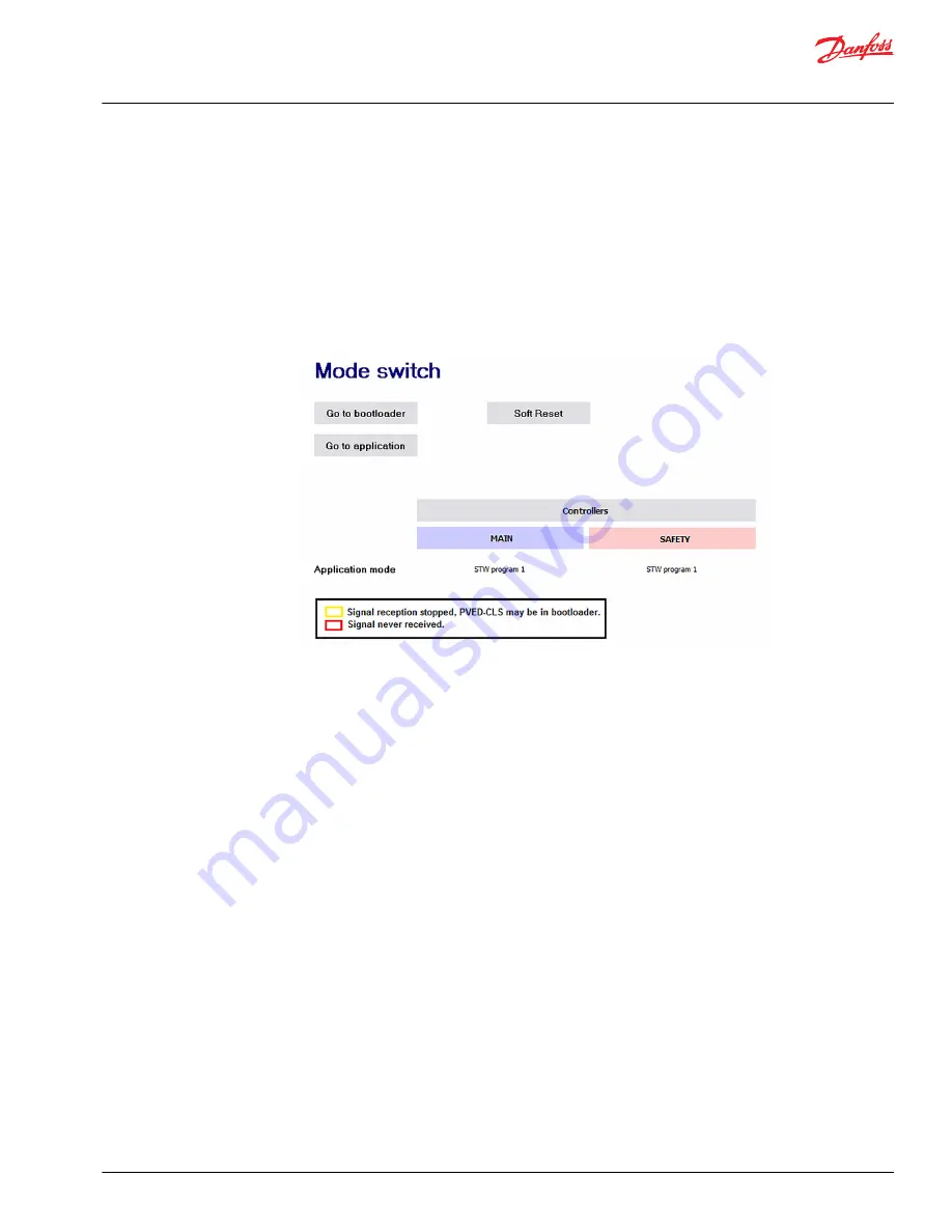
1. Open the Mode switch page.

The Mode Switch page is used to change between Bootloader and Application modes. When a

Config page is entered while in Normal View in the Service Tool, the PVED-CLS enters Bootloader
mode. To return to Application mode go to the Mode switch page and press the “Go to application”
button.

If the PVED-CLS is already in application mode (there is no red or yellow box around the Main and
Safety states) the "Go to application" button does not need to be pressed.

2. Press the "Soft Reset" button to reboot the PVED-CLS.

This may clear the Safe State if it was caused by exceeding a speed threshold or a temporarily missing

message.

If the PVED-CLS remains in safe-state mode, proceed to the 

Resolving safe-state mode with SPN and FMI

codes

 on page 42 section for further troubleshooting.

Application Guide

PVED-CLS startup guide

Troubleshooting


©

 Danfoss | October 2018

AB285975085591en-000101 | 41

Summary of Contents for PVED-CLS

Page 1: ...Application Guide PVED CLS Start up guide www danfoss com...

Page 2: ...Revision history Table of revisions Date Changed Rev October 2018 First edition 0101 Application Guide PVED CLS startup guide 2 Danfoss October 2018 AB285975085591en 000101...

Page 3: ...a 20 Production calibration flag 22 STW configuration 23 AUX configuration 27 GPS configuration 33 Auto calibration configuration 37 Advanced parameter setting Troubleshooting Resolving safe state mod...

Page 4: ...PVED CLS user manual included in firmware release package technical manuals folder Communication protocol included in firmware release package technical manuals folder PLUS 1 Service Tool user guide f...

Page 5: ...ed or latest firmware release package on the PVED CLS web page 2 Optional Request and download the PLUS 1 Service Tool under Service Tool Request heading Application Guide PVED CLS startup guide Intro...

Page 6: ...possible with the Service Tool depending on the specific revisions Please contact the Danfoss technical representative if you have concerns about changing firmware 3 Install Diagnostic Data Files of...

Page 7: ...3081 Set to match the valve type used P3082 If using EHPS enter desired turns lock to lock x100 that matches the hydraulic system P3084 Set to match OSP displacement in cubic centimeters P3086 Set to...

Page 8: ...he script to complete 2 Click Close It is mandatory to confirm that the parameters have been downloaded by the user 3 Press Approve Parameters The text will change to Approved and the page can then be...

Page 9: ...the parameter change is not described below or conditions are not met use the default values Parameter Conditions for value changes P3237 Set to match presence of GPS auto guidance controllers in sys...

Page 10: ...eshold to allow for switching steering wheel programs speed measured in km h P3252 Vehicle speed must be above this threshold to use auto guidance P3253 PVED CLS will go into safe state mode if vehicl...

Page 11: ...alue changes P3421 Set to match type of steering P3422 Change according to wheel base figure shown below dimensions measured in mm P3424 Change according to wheel base figure shown below dimensions me...

Page 12: ...ormula tan 1 WB R Approve the parameters by following the steps in PVED CLS parameter acceptance on page 8 Application Guide PVED CLS startup guide Parameter setting 12 Danfoss October 2018 AB28597508...

Page 13: ...via System Navigator Configuration SEHS Protocol Data Example parameter settings If the parameter change is not described below or conditions are not met use the default values Application Guide PVED...

Page 14: ...is sent at the rate of value x 10ms P3302 P3307 Set to over 0 if using messages to send data at the rate of value x 10ms otherwise messages are disabled P3327 Set to over 0 if using messages to send d...

Page 15: ...ess PGN s conflict with others on the CAN bus or another addressing scheme is desired P3329 Leave at default unless PGN s conflict with others on the CAN bus or another addressing scheme is desired P3...

Page 16: ...ler Set to desired Bootloader Source Address for Main Controller P0003 safety controller Set to desired Bootloader Source Address for Safety Controller Accept Boot Node ID parameters 1 Download the ch...

Page 17: ...sing the steering wheel and press the appropriate button when wheels are at the desired angle 3 Press Accept and save Values will automatically change in either the Analog Sensor Calibration Data or C...

Page 18: ...de 2 Turn the steering wheel so that Service Mode State changes to Spool Calibration Getting Armed 3 Stop turning the steering wheel and secure the wheels in a central position so that it changes to S...

Page 19: ...press the Accept and Save button Values will automatically change in Valve Calibration Data page If values need to be changed manually go to Valve Calibration Data page Application Guide PVED CLS star...

Page 20: ...P3164 If using an EHPS set the value to 700 Otherwise use default value P3166 Adjust toward 0 for smaller minimum flow in Closed Loop modes auto guidance and vice versa See deadband figure below P3168...

Page 21: ...mandatory to confirm that the parameters have been downloaded by the user 3 Press Approve Parameters The text will change to Approved and the page can then be closed Leaving the page before parameters...

Page 22: ...calibration flag has been set above 0 If an analog joystick has been selected in Peripherals Config the Joystick Calibration will need to be run to set the calibration for this too If the PVED CLS is...

Page 23: ...nd Anti drift Be sure to Download and approve parameters when complete with Steering Wheel configuration PVED CLS Steering wheel programs There are 5 steering wheel programs with identical parameters...

Page 24: ...e steering wheel program will have a fixed number of turns lock to lock Steering wheel programs can be set so that the number of turns lock to lock changes depending on the vehicle speed Example of ve...

Page 25: ...Example parameter settings Parameter Conditions for value change P3562 Distance from end stop flow starts to decrease 0 1 P3566 Distance from end stop flow stops decreasing 0 1 P3564 Max allowed flow...

Page 26: ...achine feels responsive but not jerky The cross over start and stop points P3578 and P3580 can stay at defaults unless extra anti jerk functionality is required PVED CLS anti drift Anti drift can be u...

Page 27: ...240 in the Peripherals Config page AUX Mini wheel programs Soft stop Anti jerk Anti drift Flow limitation Closed loop joystick and Open loop joystick Approve the parameters by following the steps in P...

Page 28: ...ehicles These parameters can be applied with a mini steering wheel or open loop joystick Parameter Conditions for value change P3698 P3718 See Section 11 6 Open Loop Anti Jerk in the User Manual for c...

Page 29: ...more info Parameter Conditions for value change P3690 Set to desired flow limit 1000 100 at 0 km h see graph below P3692 Set to desired flow limit y axis at desired vehicle speed in km h P3696 P3694 S...

Page 30: ...d yield a curve that can be reflected with the AUX Flow Limitation PVED CLS AUX closed loop joystick AUX Wheel Angle Limit is used with Closed Loop Joysticks to limit the maximum wheel angle as the ve...

Page 31: ...ts vs vehicle speed should yield a curve that can be mimicked with the AUX Wheel Angle Limitation function PVED CLS AUX closed loop gain AUX Closed Loop Gain sets the gain used by the Closed Loop Joys...

Page 32: ...32 Max closed loop error IR 100 10 before closed loop joystick steering is enabled PVED CLS AUX open loop joystick transfer function Open Loop Joystick transfer function scales the position of the ope...

Page 33: ...00 100 at 0 km h see graph below P3453 Set to desired vehicle speed in km h x axis at desired flow limit P3455 P3455 Set to desired vehicle speed in km h x axis at desired flow limit P3453 P3457 Set t...

Page 34: ...eld a curve that shows the demands from the auto guidance controller and that can be mimicked with the GPS Flow Limitation function PVED CLS GPS wheel angle limitation GPS Wheel Angle Limitation decre...

Page 35: ...d tipping the vehicle 3 Use the wheel angle limitation to decrease the allowed wheel angle at that speed 4 Iterate at faster speeds until an appropriate wheel angle limit is created for all vehicle sp...

Page 36: ...be triggered Set the speeds so that they increase with increasing parameter number P3484 It is highly recommended that Flow Command filter is left at the default setting P3496 GPS Algorithm Type can b...

Page 37: ...gles Automatically adjusted cylinder stroke and max steer angle values are used for vehicles where changing tires may affect the maximum steering angles decreasing because larger wheels or duals may i...

Page 38: ...set the behavior of the Auto Spool Calibration routine which finds the Closed Loop dead band edges for the spool calibration See Section 9 4 1 1 in the User Manual for more detailed descriptions of th...

Page 39: ...pool dead band tuning advice 1 During machine startup use default Auto Spool Calibration parameters as described in the calibration section 2 Manually adjust closed loop dead band edges while tuning G...

Page 40: ...e Tool to learn how to use the following pages Parameter File Interface_OEM Parameter File Interface_VPS Clone PVED CLS These files are used to export and import parameter configurations Application G...

Page 41: ...ess the Go to application button If the PVED CLS is already in application mode there is no red or yellow box around the Main and Safety states the Go to application button does not need to be pressed...

Page 42: ...fety The blue arrow shows the most recent error in the list After 16 errors are recorded new errors are written over previous errors starting at Error Record 1 2 Click the corresponding Error Record b...

Page 43: ...efore clearing the error history SEHS error occurrence The SEHS error occurrence page is the second method used to troubleshoot safe mode in PVED CLS Go to the SEHS error occurrence page via System Na...

Page 44: ...iew the contents of status messages If a yellow or red box appears around any messages of interest they are not currently being received or transmitted Follow these sub steps to resolve the issue Appl...

Page 45: ...utput Control a Press the Go to Direct Output Control Mode button b Press the Request Cut off Valve On button to enable the directional spool to move and flow to be sent to the steering cylinder c Ent...

Page 46: ...Application Guide PVED CLS startup guide 46 Danfoss October 2018 AB285975085591en 000101...

Page 47: ...Application Guide PVED CLS startup guide Danfoss October 2018 AB285975085591en 000101 47...

Page 48: ...488 2222 Danfoss Power Solutions US Company 2800 East 13th Street Ames IA 50010 USA Phone 1 515 239 6000 Danfoss Power Solutions Trading Shanghai Co Ltd Building 22 No 1000 Jin Hai Rd Jin Qiao Pudong...

Reviews: