background image

Guideline 

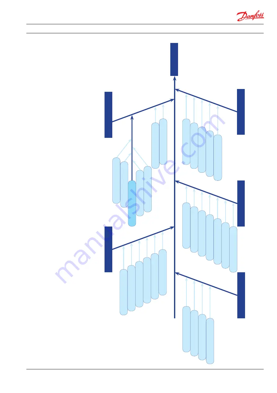
Trouble shooting guide for PAH, PAHT, PAHT C , PAHT G pumps

61

180R9379 | AQ188686503004en-000801 | PAH 2-12.5 } 07.2022

 Trouble  shooting   

fish bone chart

1.

 N

o fl

ow

/p

re

ssu

re

3. H

ig

h t

or

qu

e o

n e

l. m

ot

or

4. N

oi

se f

ro

m p

um

p

5.

 N

ois

e f

ro

m

 ins

ta

lla

tio

n

2. R

edu

ce

d fl

ow

/p

re

ss

ur

e

1.

1 D

ry r

un

ni

ng

1.

2 P

ump

 re

ve

rs

in

g

1.

3 N

o r

ot

at

io

n o

f e

le

ct

ri

c m

ot

or

1.

4 N

o r

ot

at

io

n o

f p

um

p

1.

5 A

xi

al f

or

ce o

n p

um

p s

ha

ft

1.

6 P

um

p da

mag

e

2.

1.

5 Pr

e-t

re

at

m

en

t

2.

1.

6 M

ain

 filt

ra

tio

n

2.1

  W

ea

r i

n p

um


(in

te

rnal

 le

ak

ag

e)

2.

1.

7 T

yp

e o

f fl

ui

d

2.

1.

8 H

ig

h flui

d t

emp

era

tu

re

4.

1 A

ir

 in

 flui

d

4.

2 B

le

ed

ing

 c

ond

it

ion

s of

 pu

m

p

4.

 M

in

/m

ax

 n

ominal


inl

et

 p

res

su

re

4.

4 P

um

p r

ev

er

si

ng

4.

5 H

ig

h r

ot

at

io

n s

pe

ed (

RP

M

)

4.

6 O

utl

et

 p

res

sure

5.1

  In

le

t/

ou

tle

t c

on

ne

ct

ion

(h

os

es

/p

ip

es

)

5.

 Le

ngt

h/

di

m

en

si

on

s of


inl

et

/o

ut

le

t l

in

e

5.

3 Ho

se

 st

iffn

es

s

5.

 H

os

es

/p

ip

es

 m

ou

nt

ed


di

re

ctl

y o

n f

ra

m

e

5.

 V

ib

ra

ti

on d

am

pe

r u

nd

er t

he 

el

ec

tric

 m

ot

or

3.1

  T

oo

 h

igh

 o

utl

et

 p

re

ss

ure


from

 pu

m

p

3.

3 C

on

st

an

t t

orq

ue

3.

4 W

at

er p

um

p d

am

ag

e

4.

7 S

of

t s

ta

rt

/s

to

p

PU

M

P F

AI

LE

D

3.

2 P

um

p s

ta

rt

s aga

in

st

 p

re

ss

ure

2.

2 Lo

w

 in

le

t p

re

ss

ure

2.

3 R

PM

Summary of Contents for PAH 2

Page 1: ...Operating guide PAH pumps PAH 2 12 5 Installation Operation and Maintenance Manual hpp danfoss com ...

Page 2: ... 10 Chemicals 8 4 Arrival inspection transportation handling lifting and storage 8 4 1 Arrival inspection 8 4 2 Warning 8 4 3 General safety information 8 4 4 Transport and handling 8 4 5 Return to supplier 9 4 6 Storage 9 5 Installation and commissioning 10 5 1 Important dimensions 10 5 2 Cleanliness 10 5 3 Fluid temperature 10 5 4 Electrical data 10 5 5 Local regulations 10 5 6 Pre mounting chec...

Page 3: ...unit back into operation 14 7 8 Storage of the pump 14 8 Troubleshooting and scrapping criteria 15 8 1 General safety information 15 8 2 Operational conditions which can cause pump failures 15 8 3 Mechanical failure 15 8 4 Electrical failure 15 8 5 Responsibility 15 8 6 Scrapping criteria 15 Appendices 17 1 Data sheet PAH 2 12 5 AI073186502976en 001801 19 2 Pump instruction PAH PAHT PAHT G 2 12 5 ...

Page 4: ...XXX XXXXXX04 XXX PAH 6 3 Code no 180B0023 PAH 6 3 Ex 180B6123 Serial no XXXXXX04 XXX XXXXXX04 XXX PAH 10 Code no 180B0008 PAH 10 Ex 180B6108 Serial no XXXXXX04 XXX XXXXXX04 XXX PAH 12 5 Code no 180B0007 PAH 12 5 Ex 180B6107 Serial no XXXXXX04 XXX XXXXXX04 XXX In case the pump delivered is ATEX certified the additional ATEX instruction maus also be read PUMP Type PAH 12 5 Code no 180B0007 Serial no...

Page 5: ...t mechanical and electrical parts Decommissioning the motor pump unit The pump must always be installed and used in accordance with existing national local sanitary safety regulations and laws It is the responsibility of the safety officer or the chief operator to assure compliance with all local regulations that are not taken into account in this manual Changing the pumps or pump units opera tion...

Page 6: ...th a Danger Hot sign When using an electric motor the motor must always be supplied with adequate cooling ventilation When using an electric motor together with a VFD Variable Frequency Drive the motor must be designed for operation with VFD VFD operation may increase the temperature inside the electric motor if the motor is not designed for VFD operation This can damage the motor and cause uninte...

Page 7: ...d to have sufficient space available around the pump in order to ensure easy access Sufficient space means at least 1 meter 40 inches around the pump When working with high pressures it is important to have the right space available around the pump as stated in the safety requirements It is always the system builders responsibility that the system design does not cause any kind of hazard and is ad...

Page 8: ...s that can result in damage to piping equipment and internal parts of the pump 4 Arrival inspection transportation handling lifting and storage 4 1 Arrival inspection The pump is packed in a cardboard or wood box with plugs in the port connections to protect the pump from damage during transportation When the shipment has arrived it is important to check the pump for any damages The name plate typ...

Page 9: ...truction Incorrect lifting can result in personal injury and or damage to the pump unit see appendix 2 Instruction 4 5 Return to supplier Please see maintenance chapter 7 4 6 Storage Each pump is tested before shipment and will therefore contain water For storage temperature and frost protection see appendix 2 Instruction The pumps are NOT delivered frost protected from the factory Wrong lifting P...

Page 10: ... piping must not be corroded If dirt or rust is not removed the pump and the valves can be damaged In worst case the pump can be damaged beyond repair 5 3 Fluid temperature Before start up the fluid and pump housing temperature must be within the specified temperature range listed in appendix 1 Data sheet 5 4 Electrical data Check voltage current frequency and rated power on the electric motor and...

Page 11: ...eck correct connections on the pump in outlet CP13 Check piping for possible air gaps 5 7 Lifting and positioning Lift the pump unit onto base Remember vibration dampers if needed Fasten the motor to the base See also chapter 4 Arrival inspection transporta tion handling lifting and storage 5 8 Mount the different equipment connections pipes tubes check and safety relief valves etc The hard piping...

Page 12: ... valve to minimum setting Check rotation of the high pressure pump by description in 5 15 Start high pressure pump for 2 minutes to make sure all air is out of the system Adjust pressure relief valve to working pressure Check all fittings for leakage Check the temperature switch controls The high pressure pump must stop if tempera ture is above specified set point Check the pressure switch control...

Page 13: ...ng and troubleshooting If the pump is not stopped for inspection as recommended it can lead to damage of the pump or break down See also service and warranty section in appendix 1 Data sheet and appendix 2 Instruction Danfoss offers service of the pump at the system manufacturer s location as well as we offer training in how to service the pump Quotes are offered upon request Danfoss recommends si...

Page 14: ...assembling and Assembling Instruction available at www danfoss high pressurepumps com Clean all the parts and surfaces with a fluid compatible with the materials found in the pump Wipe the parts clean and dry with a lint free clothing C Inspect all parts including shaft seal and if necessary replace them see appendix 4 Parts list D If the pump is going to be returned to Danfoss for repair or a war...

Page 15: ...r falling If water is dripping into the electric motor it can cause electric shock fire short of circuit or even death When mounting the pump vertically always mount the motor above the pump to avoid water leaking into the electric motor Electrical hazard 8 4 Electrical failure If the wiring of the electric motor is incorrect or the ground connection is missing it can cause electric shock burn dam...

Page 16: ...Operation guide Installation Operation and Maintenance Manual for PAH 2 12 5 pumps 16 180R9379 AQ188686503004en 000801 PAH 2 12 5 07 2022 ...

Page 17: ...Operation guide PAH pumps PAH 2 12 5 Appendices for Operation Installation and Maintenance Manual hpp danfoss com ...

Page 18: ...ata sheet PAH 2 12 5 AI073186502976en 001801 19 2 Pump instruction PAH PAHT PAHT G 2 12 5 1AN103586502885en 000501 33 3 Electric motor manual 180R9230 43 4 Parts list PAH 2 12 5 AX322447719905en 000401 49 5 Trouble shooting guide for PAH PAHT PAHT G PAHT 674 and PAH F pumps 59 6 Right and wrong Trouble shooting guide for water hydraulic systems 180R9042 73 ...

Page 19: ...nfoss high pressurepumps com Data sheet PAH 2 4 6 3 PAH 10 12 5 PAH 20 25 32 and PAH 50 63 70 80 100 pumps Data sheet PAH pumps PAH 2 4 6 3 PAH 10 12 5 PAH 20 25 32 and PAH 50 63 70 80 100 hpp danfoss com ...

Page 20: ...ervice 31 The data sheet is valid for PAH pumps both non ATEX and ATEX certified The ATEX certified versions are indicated with Ex in the designation The Danfoss range of PAH high pressure pumps is designed to supply water flow under high pressure for a varity of tap water applications Danfoss PAH pumps are positive displacement pumps with axial pistons that move a fixed amount of water in each cy...

Page 21: ...ump on the market Easy installation The lightest and most compact design available Pump can be installed horizontally or vertically No pulsation dampeners necessary due to extremely low pressure pulsation Powered by electric motors or combus tion engines Suitable for both boosted inlet pressure and water supply from a tank No need for cooling circuits due to very high mechanical efficiency Certifi...

Page 22: ...ilable in section 5 1000 rpm at max pressure l min 1 0 3 2 5 6 8 4 11 0 1500 rpm at max pressure l min 2 0 5 2 8 7 13 4 17 2 1200 rpm at max pressure gpm 0 4 1 0 1 8 2 7 3 5 1800 rpm at max pressure gpm 0 7 1 7 2 8 4 3 5 5 Typical motor size 1500 rpm at max pressure kW 0 9 1 7 2 6 4 5 5 6 1800 rpm at max pressure hp 1 5 2 7 4 2 7 3 9 0 Torque at max spec Nm 5 9 10 9 16 7 29 0 35 8 lbf ft 4 4 8 0 1...

Page 23: ...oretical flow l min gpm Q pmax Flows at max pressure l min and gpm see 4 1 4 4 p max Max pressure barg psig p Pressure barg psig V Displacement cm3 rev n Motor speed rpm 5 1 PAH 2 6 3 typical flow curves at max pressure 12 10 8 6 4 2 0 rpm PAH 2 0 PAH 4 0 PAH 6 3 l min 7 0 0 9 0 0 1 1 0 0 1 3 0 0 1 5 0 0 1 7 0 0 1 8 0 0 3 2 5 2 1 5 1 0 5 0 rpm PAH 2 0 PAH 4 0 PAH 6 3 gpm 7 0 0 9 0 0 1 1 0 0 1 3 0 ...

Page 24: ...ure 19 23 21 17 15 13 11 9 7 5 3 0 1 2 3 4 5 6 l min gpm 1 1 0 0 9 0 0 1 3 0 0 1 5 0 0 1 7 0 0 1 8 0 0 7 0 0 rpm PAH 12 5 PAH 10 PAH 12 5 PAH 10 rpm 1 1 0 0 9 0 0 1 3 0 0 1 5 0 0 1 7 0 0 1 8 0 0 7 0 0 19 23 21 17 15 13 11 9 7 5 3 0 1 2 3 4 5 6 l min gpm 1 1 0 0 9 0 0 1 3 0 0 1 5 0 0 1 7 0 0 1 8 0 0 7 0 0 rpm PAH 12 5 PAH 10 PAH 12 5 PAH 10 rpm 1 1 0 0 9 0 0 1 3 0 0 1 5 0 0 1 7 0 0 1 8 0 0 7 0 0 ...

Page 25: ...he flow curves in item 5 you can deter mine the rpm of the pump at the desired flow The required torque is calculated as follows V x p M 62 8 x η To determine the correct motor size both the power and torque requirement must be verified The mechanical efficiency of the pump at max pressure is as follows PAH 2 4 6 3 0 82 PAH 10 12 5 0 9 PAH 20 25 32 50 63 70 80 100 0 95 P Power kW M Torque Nm η Mec...

Page 26: ...on efficiency This means that out of 100 000 particles that enter such filters 50 000 particles pass right through them compare this to precision depth filters that are 99 98 efficient and only allow 20 of the same 100 000 particles to pass through For more information on the importance of proper filtration including explanation of filtration principles definitions and guidance on how to select th...

Page 27: ...monitoring temperature switch 4 between the filter and the pump on either side of the monitoring pressure switch Set the temperature value accord ing to technical data item 4 The monitor ing temperature switch stops the pump if inlet temperature is higher than the set value E Hoses Always use flexible hoses 5 to minimize vibrations and noise F Inlet pressure In order to eliminate the risk of cavit...

Page 28: ...re value according to technical data item 4 The monitoring temperature stops the pump if inlet temperature is higher than the set value E Hoses Always use flexible hoses 6 to minimize vibrations and noise F Inlet pressure In order to eliminate the risk of cavitation and other pump damage pump inlet pressure must be maintained according to specifications described in item 4 technical data G Non ret...

Page 29: ...Data sheet PAH 2 4 6 3 PAH 10 12 5 PAH 20 25 32 and PAH 50 63 70 80 100 pumps 180R9379 AQ188686503004en 000801 PAH 2 12 5 29 Danfoss DCS im 2022 07 8 Dimensions and connections 8 1 PAH 2 6 3 ...

Page 30: ...Data sheet PAH 2 4 6 3 PAH 10 12 5 PAH 20 25 32 and PAH 50 63 70 80 100 pumps 30 180R9379 AQ188686503004en 000801 PAH 2 12 5 Danfoss DCS im 2022 07 8 2 PAH 10 12 5 ...

Page 31: ...commendations concerning system design and operation are not followed In our experience poor filtration is the number one cause of pump damage Other factors that affect pump performance and lifetime include running the pump at speeds outside specifications supplying the pump with water at temper atures higher than recommended running the pump at inlet pressures outside specifications running the p...

Page 32: ... Danfoss DCS im 2022 07 AI073186502976en 001901 32 ...

Page 33: ...danfoss high pressurepumps com Instruction PAH PAHT PAHT G 2 6 3 PAH PAHT PAHT G 10 12 Instruction PAH PAHT pumps PAH PAHT 2 12 5 hpp danfoss com ...

Page 34: ... 3 1 Mounting 38 3 2 Direction of rotation 38 3 3 Orientation 38 3 4 Protection from too high pressures 39 3 5 Connections 39 4 Initial start up 40 5 Operation 40 5 1 Water quality 40 5 2 Temperature 40 5 3 Pressure 40 5 4 Dry running 40 5 5 Disconnection 40 5 6 Storage 40 5 6 1 Water hydraulic systems water recirculated 40 5 6 2 Open ended systems with water supply from tank 41 5 6 3 Open ended s...

Page 35: ...ccording to technical data item 4 The monitoring temperature stops the pump if inlet temperature is higher than the set value E Hoses Always use flexible hoses 6 to minimize vibrations and noise F Inlet pressure In order to eliminate the risk of cavitation and other pump damage pump inlet pressure must be maintained according to specifications described in item 4 technical data G Non return valve ...

Page 36: ...re switch 4 between the filter and the pump on either side of the monitoring pressure switch Set the temperature value accord ing to technical data item 4 The monitor ing temperature switch stops the pump if inlet temperature is higher than the set value E Hoses Always use flexible hoses 5 to minimize vibrations and noise F Inlet pressure In order to eliminate the risk of cavitation and other pump...

Page 37: ...es of the applied materials Main filter must have a fineness of 10 µm abs β10 5 000 The pressure loss across the filter should be monitored Please contact the Danfoss Sales Organiza tion for further filter details Water tank Must be made of corrosion proof material such as stainless steel or plastic and must be sealed to prevent entrance of impurities from the environ ment Automatic pressure equal...

Page 38: ...the elastic coupling without use of tools Please take care to observe the recommended length tolerances of the chosen coupling as an axial force on the pump shaft must be avoided 3 2 Direction of rotation Is indicated by means of an arrow at the label of the pump A Elastic coupling B Bell housing C Motor shaft We recommend a separation wall to separate the inlet from the outlet end of the tank Mon...

Page 39: ...ening characteristics of the valve must not result in peak pressures higher than 200 bar 2900 psi The valve outlet must not be connected directly to the pump suction line It shall be connected directly to the tank PAH PAHT 2 6 3 PAH PAHT 10 12 5 P T C P T C Thread size G 1 4 x 11 G 1 2 x 15 M6 Allen key 4 mm G 3 8 x 15 G 3 4 X 17 G 1 4 NV6 14 deep Max tighten torque 25 Nm 25 Nm 5 Nm 25 Nm 25 Nm 15...

Page 40: ...ssure gauge on the high pressure side 5 4 Dry running When running the pump must always be connected to the water supply in order to avoid damage if it should run dry In systems with water tank it is recommended to build in a level gauge in the tank to avoid the risk of running dry 5 5 Disconnection If the inlet line is disconnected from the water supply the pump will be emptied of water through t...

Page 41: ...n for additional 8 000 hours the following parts will have to be inspected Pistons Retainer plate ball and bearing Valve plate Port plate Sealings If there are any wear marks on the parts they need to be replaced If service inspection due to the application is complicated the plant operator can decide to extend the service interval by evaluating the following deviations Sound does the pump have an...

Page 42: ... Danfoss DHS im 2022 02 180R9379 AQ188686503004en 000701 PAH 2 12 5 42 ...

Page 43: ...M a n u a l Electric Motors Motor Manual hoyermotors com ...

Page 44: ...that the mounting conditions do not cause resonance with the rotational frequency and the doubled supply frequency Only mount or remove drive components pulley coupling etc using suitable tools never hit the drive components with a hammer as this will cause damage to the bearing The motor are balancing with half key ensure that the drive components are also the same Correct alignment is essential ...

Page 45: ...alues The table values are based on an ambient temperature of 25 C The values must be halved for every 15K increase in bearing temperature Higher speed operations e g frequency converter drive will require shorter greasing intervals Typically doubling the speed will reduce the values by 50 Special note for Atex Zone 22 and nA motors Designation of motor according to IEC standard II 3D Ex tc IIIB T...

Page 46: ...46 180R9379 AQ188686503004en 000801 PAH 2 12 5 07 2022 Connection diagram Anschlußdiagram Anslutningdiagramm Forbindelsesdiagram Aansluitdiagram Connection Conexión Collegamento Schemat polacsen ...

Page 47: ...47 180R9379 AQ188686503004en 000801 PAH 2 12 5 07 2022 ...

Page 48: ...dsberger Straße 155 80687 München T 49 89 700 88 235 F 49 89 543 56 333 germany hoyermotors com hoyermotors com Sweden Liljeholmsstranden 5 PO box 44017 SE 100 73 Stockholm T 46 8 446 877 13 sweden hoyermotors com hoyermotors com Benelux Vasteland 78 3011 BN Rotterdam Tel 31 10 420 35 20 Fax 31 10 420 44 51 benelux hoyermotors com hoyermotors com Korea 302ho Code square 3150 1 Daejeo 2 dong Gangse...

Page 49: ...hpp danfoss com Parts list PAHC 2 6 3 pumps Parts list PAH pumps PAH 2 4 6 3 10 12 5 hpp danfoss com ...

Page 50: ...01 PAH 2 12 5 07 2022 Table of Contents Contents 1 General 51 2 Spare parts list for PAH 2 52 2 1 Exploded view for PAH 2 53 3 Spare parts list for PAH 4 6 3 54 3 1 Exploded view for PAH 4 6 3 55 4 Spare parts list for PAH 10 12 5 56 3 1 Exploded view for PAH 10 12 5 57 ...

Page 51: ...t provides an overview of the content of the various service sets as well as exploeded views for both non ATEX and ATEX certified pumps ATEX certified pumps are indicated by Ex in the designation 1 General Non ATEX ATEX PAH 2 PAH 2 Ex PAH 4 PAH 4 Ex PAH 6 3 PAH 6 3 Ex PAH 10 PAH 10 Ex PAH 12 5 PAH 12 5 Ex ...

Page 52: ...316 X 31 1 Swash plate AISI 431 X 32 1 Screw AISI 304 X 33 1 Washer AISI 304 X 34 1 Pin AISI 316 X 61 1 Cylinder barrel AISI 431 PEEK X 62 1 Spring AISI 304 X X 65 1 Retainer plate AISI 431 X X 66 5 Piston AISI 431 PEEK X X 67 1 Key AISI 316Ti X 69 1 Stop PEEK X X 91 1 Port plate AISI 304 PEEK X 92 1 Valve plate AISI 431 X 93 5 Back up ring PTFE X X 94 5 O ring NBR X X 121 1 Port flange AISI 304 P...

Page 53: ...Parts list PAH 2 4 6 3 10 and 12 5 53 180R9379 AQ188686503004en 000801 PAH 2 12 5 07 2022 2 1 Exploded view for PAH 2 ...

Page 54: ...w AISI 304 X X 33 1 Washer AISI 304 X X 34 1 Pin AISI 316 X X 61 1 Cylinder barrel AISI 431 PEEK X 62 1 Spring AISI 304 X 63 1 Spring guide PEEK X 64 1 Retainer ball AISI 431 X 65 1 Retainer plate AISI 431 X 66 5 Piston AISI 431 PEEK X 67 1 Key AISI 316Ti X 91 1 Port plate AISI 304 PEEK X 92 1 Valve plate AISI 431 X 93 5 Back up ring PTFE X X 94 5 O ring NBR X X 121 1 Port flange AISI 304 PEEK 122...

Page 55: ...Parts list PAH 2 4 6 3 10 and 12 5 55 180R9379 AQ188686503004en 000801 PAH 2 12 5 07 2022 3 1 Exploded view for PAH 4 6 3 ...

Page 56: ...31 1 Swash plate AISI 431 X X 32 1 Screw AISI 304 X X 33 1 Washer AISI 304 X X 34 1 Pin AISI 316 X X 61 1 Cylinder barrel AISI 431 PEEK X X 62 1 Spring AISI 316Ti X X 63 1 Spring guide PEEK X X 64 1 Retainer ball PEEK X X 65 1 Retainer plate AISI 304 X X 66 5 Piston AISI 431 PEEK X X 67 1 Key AISI 316Ti X 91 1 Port plate AISI 304 PEEK X 92 1 Valve plate AISI 431 X 93 5 Back up ring PTFE X X 94 5 O...

Page 57: ...Parts list PAH 2 4 6 3 10 and 12 5 57 180R9379 AQ188686503004en 000801 PAH 2 12 5 07 2022 3 1 Exploded view for PAH 10 12 5 ...

Page 58: ... Danfoss DCS im 2020 09 AX322447719905en 000401 58 Danfoss A S High Pressure Pumps Nordborgvej 81 DK 6430 Nordborg Denmark ...

Page 59: ...hpp danfoss com Guideline Trouble shooting guide for PAH PAHT PAHT C PAHT G PAHT 674 and PAH F pumps Guide line PAH PAHT PAHT C PAHT G pumps Trouble shooting guide hpp danfoss com ...

Page 60: ... PAHT PAHT C PAHT G pumps 60 180R9379 AQ188686503004en 000801 PAH 2 12 5 07 2022 Table of Contents Table of Contents Trouble shooting fish bone chart 61 1 No flow no pressure 62 2 Reduced flow reduced pressure 63 3 High torque on electric motor 64 4 Noise from pump 65 5 Noise from installation 66 6 Typical signs of wear 67 6 1 Valve plate 67 6 2 Port plate 68 6 3 Swash plate 68 ...

Page 61: ...t 2 1 6 Main filtration 2 1 Wear in pump internal leakage 2 1 7 Type of fluid 2 1 8 High fluid temperature 4 1 Air in fluid 4 2 Bleeding conditions of pump 4 3 Min max nominal inlet pressure 4 4 Pump reversing 4 5 High rotation speed RPM 4 6 Outlet pressure 5 1 Inlet outlet connections hoses pipes 5 2 Length dimensions of inlet outlet line 5 3 Hose stiffness 5 4 Hoses pipes mounted directly on fra...

Page 62: ... started 1 3 6 Check that the monitor switches are working correctly 1 3 7 Disconnect pump from electric motor and check that the motor is capable of running with no load If motor type relay or the electrical fuse is blown check that electric motor is sized correctly 1 4 No rotation of pump 1 4 1 Ensure that coupling between electric motor and pump is connected 1 4 2 Check if coupling is damaged 1...

Page 63: ...ing the piston is very worn The filters can be bypassed even if they are correctly mounted Some filters can create channelling where particles can pass through the filter in tunnels String wounded filters are typically channelling filters A string wound filter may have a filtration efficiency of only 50 which will cause internal wear and must always be followed by a main filter Insufficient filtra...

Page 64: ...2 2 Check internal parts see item 2 1 3 2 3 Systems with more than one electric motor installed Start motors simultaneously Pumps run in parallel with cascade start may switch off the motor relay due to too high torque caused by high outlet pressure 3 3 Constant torque 3 3 1 Please contact Danfoss High Pressure Pumps sales office If the electric motor is too small for the pump it cannot provide su...

Page 65: ...g is broken or worn See 1 No flow item 1 2 Pump reversing WARNING The pump must not run without water for more than a few seconds If the pump takes in water from the high pressure outlet line it builds up pressure and will eventually be damaged If pump rotates in wrong direction it will take in water from the high pressure outlet line Pressure will be built up inside the pump and it will eventuall...

Page 66: ...r too many bends may create too fast flow turbulence through the pipes and thus increase the noise level 5 3 Hose stiffness 5 3 1 Use a more flexible hose Too stiff hoses cannot dampen the small pressure pulsations from the pump and subsequently vibrations occur in the system plant 5 4 Hoses pipes mounted directly on frame 5 4 1 Mount the connections to the frame by a vibration dampener mounting p...

Page 67: ...ve plate has scratches and or a polished surface Even small scratches will give a loss of flow Picture 3 A good way to identify a worn valve plate is to hold a straight knife edge over the valve plate When holding it up to the light it will be possible to see any space between the knife edge and the valve plate See picture 3 If any light can be seen between the two arrows on the picture the valve ...

Page 68: ... check See item 6 1 picture 3 6 2 Port plate 6 3 Swash plate Picture 1 If the swash plate is polished 360 it is an indication of insufficient filtration The surface of the swash plate must be plane and even at same level all over To check this please see item 6 1 picture 3 If the surface has any marks scratches it is worn damaged and a new one is required Please contact Danfoss High Pressure Pumps...

Page 69: ...Guideline Trouble shooting guide for PAH PAHT PAHT C PAHT G pumps 69 180R9379 AQ188686503004en 000801 PAH 2 12 5 07 2022 ...

Page 70: ...Guideline Trouble shooting guide for PAH PAHT PAHT C PAHT G pumps 70 180R9379 AQ188686503004en 000801 PAH 2 12 5 07 2022 ...

Page 71: ...Guideline Trouble shooting guide for PAH PAHT PAHT C PAHT G pumps 71 180R9379 AQ188686503004en 000801 PAH 2 12 5 07 2022 ...

Page 72: ...Danfoss A S High Pressure Pump Nordborgvej 81 DK 6430 Nordborg Denmark Danfoss DCS im 11 2019 521B1475 DKCFN PI 012 R2 02 72 ...

Page 73: ...RN LIVING POSSIBLE danfoss high pressurepumps com Right and wrong Trouble shooting guide for water hydraulic systems Service guide Right and wrong Trouble shooting guide for water hydraulic systems hpp danfoss com ...

Page 74: ...load may damage the pump Pump location 4 Pump always to be placed below water surface level Pump location above water surface level will cause damage Water supply 7 System to be filled via filter Filling system with unfiltered water causes damage 6 Pressure Relief valve Pressure relief valve to be mounted vertically or with vertical outlet and connected to return hose or tank Coupling the pressure...

Page 75: ...oo much grease may develop biofilm causing operational failures Water supply 13 Fill system with water before starting to ensure lubrication and cooling Starting without water will cause damage Coupling 12 Ensure always to have 3 mm distance between coupling flanges Insufficient distance and or misalign ment between the coupling flanges will damage the pump min 3 mm 0 mm Assembly of coupling 11 Th...

Page 76: ... bleed the system without pressure by opening the bypass valve 3 Add the cleaning agent to give 3 agent water solution 4 Run the system for 60 min and activate all components as often as possible to ensure effective flushing with the cleaning agent 5 Empty the system of the cleaning agent solution Flushing procedure 6 Fill cold water through the return filter and bleed the pump Power Packs PPH 4 6...

Page 77: ...Is the control light for low pump suction pressure on The filter is clogging Is the power supply ok Are control lights on Is the filter clogged Is the filter control light on Is water coming through the filter Replace filter element Turn on the tap for water supply Replace filter element A blown fuse or short circuit Check power supply and fuses and contact electrician Contact serviceman Stamp No ...

Page 78: ...filter clogged Is the filter control light on Replace filter element Contact serviceman Stamp Fill water into the system Trace leakage if any A blown fuse or short circuit Check power supply and fuses and contact electrician At temperatures higher than 50 o the pump drive cuts out Consequently the cooler must be checked cleaned Is the electric motor of the pump unit rotating No 78 180R9379 AQ18868...

Page 79: ...79 180R9379 AQ188686503004en 000801 PAH 2 12 5 07 2022 ...

Page 80: ... Danfoss DCS im 2022 07 180R9379 AQ188686503004en 000801 PAH 2 12 5 80 ...

Reviews: