Manual
15
BC251686497767en-US0801
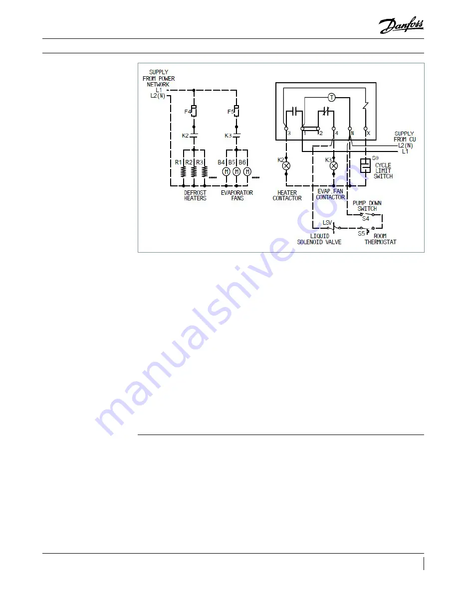
Sequence of operation – Field wiring
Sequence of operation
Refrigeration Cycle
1. Defrost timer is powered by the condensing
unit, connecting the supply to terminal “1” and
“N”.
2. The fan delay and the defrost termination
thermostat is closed in the fan delay position
and open in the defrost termination position.
The evaporator fan(s) run continuously.
3. The defrost heaters are off during refrigeration
cycle.
4. The room thermostat closes when the
temperature rises above the desired setting.
5. The liquid line solenoid valve(LSV) gets
energized and opens to allow the liquid
refrigerant to flow through the evaporator.
6. The low-pressure control switch closes when the
suction pressure rises above the cut-in setting.
7. The compressor contactor gets energized and
supply power to allow the compressor and
condenser fan to run.
8. The room temperature gradually decreases to
the desired temperature.
9. Once the desired temperature is attained, the
thermostat opens and the liquid line solenoid
closes, it will in turn stop the refrigerant flow
through the evaporator.
10. Suction pressure decreases and the
compressor contactor opens when the
pressure drops below the cut-out setting on
the low-pressure control. The compressor and
condenser fan stop running.
11. This cycle is repeated as many times as
necessary to satisfy the room thermostat.
12. Frost may form on the evaporator coil until the
defrost cycle is initiated.
Defrost Cycle
1. The defrost cycle starts automatically by the
timer at predefined intervals. Typical settings
are between two and four defrost cycles per day
for freezers. For heavier frost loads additional
settings may be required.
2. Contacts “2” to “4” opens in the defrost timer and
disconnects the circuit to the room thermostat,
liquid line solenoid, and evaporator fan motors.
This will lead the compressor to pump down
and shut-off. At the same time, Contacts “1”
to “3” closes in the timer and it will allow the
defrost heater to start through the heater
contactor.
3. The defrost heaters rise the temperature of the
coil to 32˚F triggering the frost to melt of the
coil.
4. When the coil temperature rises to 45˚F to 55˚F,
the cycle limit switch closes and it energizes
the Liquid line solenoid valve to allow the
refrigeration cycle to begin again.
Summary of Contents for OP-HJZM
Page 17: ......


