Manual
7
BC251686497767en-US0801
Never pressurize the circuit with oxygen or dry
air. This could cause fire or explosions.
• Do not use dye for leak detection.
• Perform a leak detection test on the complete
system.
• The maximum test pressure is 465psi.
• When a leak is discovered, repair the leak and
repeat the leak detection test.
• Never use the compressor to evacuate the
system.
• Connect a vacuum pump to both the LP and HP
sides.
• Pull down the system under a vacuum of 500 µm
Hg (9.7psi) absolute.
• Do not use an ohmmeter nor apply power to the
compressor while it is under vacuum as this may
cause internal damage.
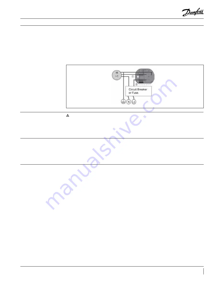
(If FSC fails, it is possible to run the fan motor full
speed)
1. Disconnect the condensing unit from power
supply.
2. Remove wire 1 from FSC.
3. Remove wire 2 from FSC.
4. Connect both wires together.
5. Make sure the connection is well insulated and
not exposed to rain or in contact with, metallic
parts.
6. Connect the condensing unit back to power
supply.
Leak detection
Fan speed controller
bypass
Vacuum dehydration
Fig.6
Installation & Maintenance
• Switch off the system and isolate the main power
supply.
• Ensure that power supply cannot be switched on
during installation.
• All electrical components must be selected as
per local standards and unit requirements.
• Refer to wiring diagram for electrical connections
details.
• Ensure that the power supply corresponds to the
unit characteristics and that the power supply
is stable (nominal voltage ±10 % and nominal
frequency ±2.5 Hz).
• Dimension the power supply cables according to
unit data for voltage and current.
• Protect the power supply and ensure correct
earthing.
• Make the power supply according to local
standards and legal requirements.
• The unit includes high and low-pressure switches
which, when activated, cut the power supply
to the compressor. Parameters for high and
low-pressure cut-outs are to be adjusted by
the installer, depending on the compressor
model, refrigerant and application. For units
with a 3-phase scroll compressor, correct phase
sequence for compressor rotation direction shall
be observed.
• Determine the phase sequence by using a phase
meter to establish the phase order of line phases
L1, L2 and L3.
• Connect line phases L1, L2 and L3 to main switch
terminals T1, T2 and T3, respectively.
Electrical connections
Summary of Contents for OP-HJZM
Page 17: ......


