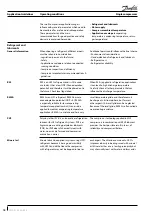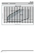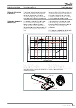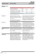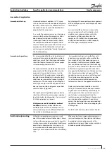
Electrical data, connections and wiring
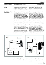
Fuses ..................................................................................................F1
Compressor contactor ................................................................. KM
Control relay ................................................................................... KA
Safety lock out relay .......................................................................KS
Optional short cycle timer (3 mins) ......................................180 s
External overload protection .......................................................F2
Pump-down pressure switch .......................................................LP
High-pressure safety switch ........................................................HP
Control device .................................................................................TH
Liquid line solenoid valve ........................................................ LLSV
Discharge gas thermostat/thermistor...................................DGT
Fused disconnect ...........................................................................Q1
Motor safety thermostat ............................................................thM
Compressor motor ..........................................................................M
Motor protection module ........................................................MPM
Thermistor chain...............................................................................S
Safety pressure switch .................................................................LPS
Legend
MLM/MLZ116
A1
A3
A2
MPM
S
LPS
Wiring diagram with pump-down cycle
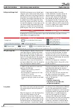
LP
A1
A3
A2
MPM
S
KS
Wiring diagram without pump-down cycle
LPS
Suggested wiring diagrams logic
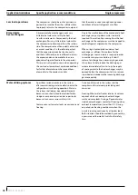
Motor protection
Compressor model
Overheating
protection
Over current
protection
Locked rotor
protection
Phase reversal protection
MLM/MLZ116
Electronic module located in terminal box
Compressor models MLM/MLZ116 are delivered
with a pre-installed motor protection module
inside the terminal box. This device provides
for efficient and reliable protection against
overheating/overloading/phase loss/reversal.
The motor protector comprises a control module
and PTC sensors embedded in the motor
winding. The close contact between thermistors
and windings ensures a very low level of thermal
inertia.
The motor temperature is being constantly
measured by a PTC thermistor loop connected
on S1-S2. If any thermistor exceeds its response
temperature, its resistance increases above the
trip level (4,500 Ω) and the output relay then
trips – i.e. contacts M1-M2 are open. After cooling
to below the response temperature (resistance
< 2,750 Ω), a 5-minute time delay is activated.
After this delay has elapsed, the relay is once
again pulled in – i.e. contacts M1-M2 are closed.
The time delay may be cancelled by means
of resetting the mains (L-N -disconnect) for
approximately 5 sec.
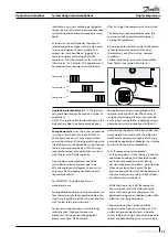
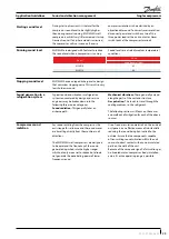
A red/green twin LED is visible on the module. A
solid green LED denotes a fault-free condition.
A blinking red LED indicates an identifiable fault
condition:
PTC overheat
Appr. 1 second
Delay timer active (after PTC over temp.)
Appr. 1 second
15
FRCC.PC.035.A5.02
Application Guidelines
Single compressors


