MAKING MODERN LIVING POSSIBLE
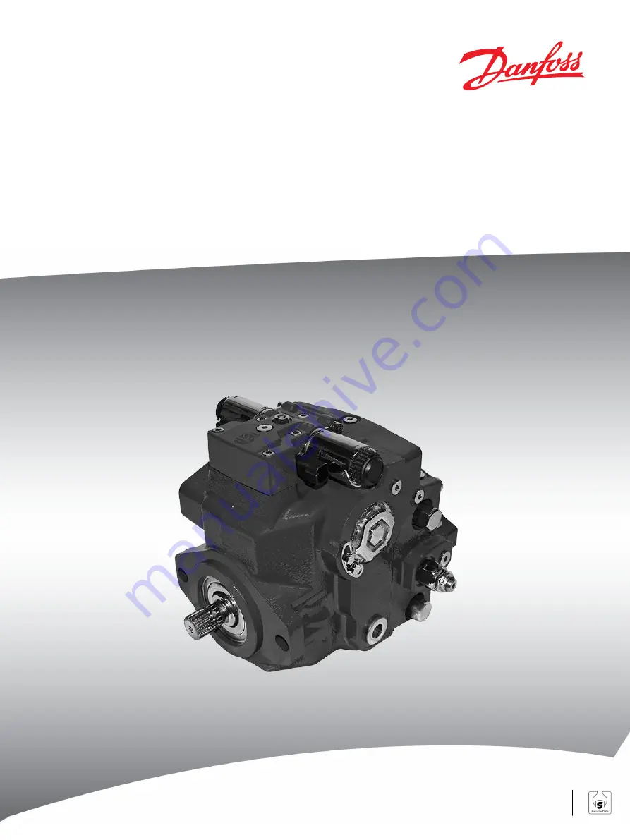
Repair Instructions
Closed Circuit Axial Piston Pumps
H1 45/53/60/68
powersolutions.danfoss.com
Page 1: ...MAKING MODERN LIVING POSSIBLE Repair Instructions Closed Circuit Axial Piston Pumps H1 45 53 60 68 powersolutions danfoss com...
Page 2: ...generic BC June 2011 add protection shield for automotive control BB October 2010 add 060 068 BA August 2010 new back page AH March 2010 add automotive control AG February 2010 Fix Osaka address AF A...
Page 3: ...r Block Kit Removal 15 Servo Sleeve Removal 16 Servo Piston Removal 17 Swashplate and Swashplate Bearing Removal 17 Servo Piston Disassembly 18 Cylinder Kit 19 Disassemble the cylinder block kit 19 Bl...
Page 4: ...Pressure Limiter Installation 41 HPRV Valve Installation 41 Optional Displacement Limiter Installation 42 Control Assembly 43 Control Installation 44 MDC Control 44 Reassembly 47 Automotive Control In...
Page 5: ...rs remove the unit from the vehicle machine Chock the wheels on the vehicle or lock the mechanism to inhibit movement Be aware that hydraulic fluid may be under high pressure and or hot Inspect the ou...
Page 6: ...cleaning solvents are flammable To avoid possible fire do not use cleaning solvents in an area where a source of ignition may be present Fluid under pressure W Warning Escaping hydraulic fluid under p...
Page 7: ...ark orientation for reinstallation Parallelism specification Torque specification External hex head Press in press fit Internal hex head Pull out with tool press fit Torx head Cover splines with insta...
Page 8: ...rrier Remove shaft seal bearing J150 J100 J200 J250 J260 J275 J300 E101 403E Input Shaft 1 Pull the shaft with bearing out of the pump If necessary tap lightly on the shaft to dislodge it from the int...
Page 9: ...200 from top of swashplate 4 If necessary remove the screen D084 C Caution Screen D084 may be loose and fall out of control Take caution not to lose it 5 If necessary remove orifices F100 using a 3 mm...
Page 10: ...ool dimensions Push down on plug and turn 45 degrees counterclockwise Discard plugs Wax seals will be destroyed when the plugs are removed Do not damage the housing in the plug sealing area 3 Use a 5...
Page 11: ...iary Pad or End Cover Removal Remove auxiliary pump if present 1 Position pump so end cover K100 or auxiliary pad is on top 2 Remove end cover auxiliary pad screws K400 using an 8 mm internal hex wren...
Page 12: ...1 406E K500 S100 S300 S200 K200 K150 K400 10 mm K100 S300 S250 G450 G450 Charge Pump Removal 1 Remove charge pump outer ring S150 and gearset S100 2 Remove valve plate S250 with seal S300 Discard seal...
Page 13: ...ght and left pressure settings are different Tag each valve for later re assembly Remove pressure limiter E101 415E 14 mm L300 L400 L022 Charge Pressure Relief Valve Removal Using a 22 mm wrench remov...
Page 14: ...wrench 2 Remove four endcap screws G350 using a 10 mm internal hex wrench 3 Carefully remove the endcap G100 and valveplate C025 Valveplate may be stuck to endcap Alignment pin C020 may remain in end...
Page 15: ...der block assembly C010 2 Set cylinder block and components on a clean dry surface C Caution Do not scratch the running surfaces of the cylinder block or slippers Scratches in these surfaces can lead...
Page 16: ...g plates E300 3 Using a 3 4 inch deep socket unthread the servo sleeves E600 from each side of the pump Servo piston will be loose after servo cylinders are removed Discard O rings E250 C Caution Do n...
Page 17: ...ssembly E100 Remove servo piston P108 489E E100 Swashplate and Swashplate Bearing Removal 1 Lift the swashplate D070 out by grasping the swashplate pin Swashplate bearings will remain on the swashplat...
Page 18: ...bearing and replace with new style bearing Servo Piston Disassembly 1 Remove and discard seals E025 2 Remove slider block E015 Servo E100 is available as an assembly only Seals E025 and slider block...
Page 19: ...k spring washer C35 to compress the block spring C30 Compress the spring enough to safely remove the spiral retaining ring C45 While maintaining pressure unwind the spiral retaining ring Carefully rel...
Page 20: ...Disassemble cylinder block kit E101 395E C45 C35 C30 C40 C05 C25 C15 C20 C10 C50 Repair Instructions H1 45 53 60 68 Closed Circuit Axial Piston Pumps Disassembly 20 520L0957 Rev CB September 2014...
Page 21: ...assemblies with excessive end play Minimum slipper foot thickness and maximum axial end play are given in ReWork Specifications 520L1033 Ball Guide Slipper Retainer and Hold Down Pins Ensure ball guid...
Page 22: ...e shaft and its splines are straight and free of damage or heavy wear Inspect the shaft surface where it meets the shaft seal Replace the shaft if a groove exists at the sealing land surface where it...
Page 23: ...s running face If you observe any discoloration or burn marks replace the valve plate Run a fingernail or pencil tip across the diameter of the sealing land surface see illustration You should feel no...
Page 24: ...arefully for wear or cracks Replace if damaged Inspect endcap P106 223E End cap rework specifications are given in ReWork Specifications 520L1033 Housing Inspect the housing to ensure that it is clean...
Page 25: ...imiter valve E101 435E HPRV Valve HPRV valves are available as complete units only If you suspect valve malfunction replace the valve s and test pump operation Replace O rings before reassembly Pressu...
Page 26: ...by hand and feel for roughness Replace cradle bearings if scratched warped or worn Replace cradle bearings as a pair Inspect cradle bearings P108 490E D075 045 053 D075 045 053 D070 060 068 D070 060...
Page 27: ...vo Piston Assembly Inspect slider block for wear or damage Replace if necessary Inspect springs for warping or cracking Replace entire assembly if springs are damaged Inspect servo piston for wear cra...
Page 28: ...a new unit and test pump If necessary you may remove and clean the control orifices Use a 3 mm internal hex wrench Torque to 2 5 N m 1 8 lbf ft Remove and replace the screen if it is clogged If you s...
Page 29: ...00 E101 420E Installation sleeve M 1 Orient pump with the mounting flange pointing up 2 Using an adequate press press the bearing J150 onto the shaft J100 and install the retaining ring J200 Ensure th...
Page 30: ...Installation 1 Position housing as shown in illustration 2 Coat the cradle bearings with hydraulic fluid and install them into the pump housing Fit retaining pins into holes in housing If cradle bear...
Page 31: ...le swashplate bearing If pump with old style bearing is being repaired discard old style bearing and replace with new style bearing 060 068 P108 491E Incorrect screen orientation Correct screen orient...
Page 32: ...r to resize the seals before installing servo piston 2 Lubricate and install slider block E015 Install slider block P106 235E Assemble servo piston E100 E101 432E E025 E015 Seal O ring E025 Seal O rin...
Page 33: ...ervo cylinder Do not compress servo piston springs C Caution Do not allow loose servo piston to damage internal machined surfaces of pump Do not damage seals when installing servo cylinders Install se...
Page 34: ...ury Compressing the block spring requires about 350 to 400 N 80 to 90 lbf Use a press sufficient to maintain this force with reasonable effort Ensure the spring is secure before attempting to install...
Page 35: ...C010 Timing Pin and Endcap Bushing Installation 1 Install timing pin C020 in endcap as shown Orient slot away from valve plate Install the alignment pins B010 in housing Measure pin insertion depth to...
Page 36: ...ing thickness 045 053 34 mm 1 3 in 060 068 40 mm 1 5 in 045 053 34 990 0 003 mm 48 mm 1 9 in 1 3775 0 0001 in 060 068 40 987 mm 1 6136 in Go 045 053 35 085 0 003 mm 1 3813 0 0001 in 060 068 41 088 mm...
Page 37: ...t bend or warp the gasket in an attempt to straighten it This may damage the embossing which is not visible under the rubber coating 5 Install endcap Using a 10 mm internal hex wrench install cap scre...
Page 38: ...Lubricate valve plate S250 and install in same orientation as when it was removed 2 Lubricate and install outer ring S150 and charge pump gearset S100 Lubricate and install coupling K200 3 Lubricate a...
Page 39: ...10 mm internal hex wrench Torque to 92 N m 68 lbf ft Follow torque sequence below Ensure proper torque on aux pad screws K400 If necessary replace screws 3 Install auxiliary pump or seal K250 and cove...
Page 40: ...250 K350 18 mm 77 Nm 58 lbf ft K300 K400 8 mm 92 Nm 68 lbf ft K350 17 mm 48 Nm 35 lbf ft Charge Pressure Relief Valve Installation 1 Install new O ring V024 2 Using a 22 mm wrench install the charge p...
Page 41: ...60 68 Closed Circuit Axial Piston Pumps Service Manual 520L0958 for instructions on adjusting pressure limiter Install pressure limiter E101 425E 14 mm L300 L400 30 N m 22 lbf ft L022 HPRV Valve Inst...
Page 42: ...model code See to table below for displacement change per turn Run screw in until it contacts the servo piston then back out the appropriate number of turns Install the displacement limiter E101 427E...
Page 43: ...Replace screen D084 if previously removed Drawing shows proper screen orientation If you suspect coil malfunction remove the coil D025B by removing the plastic nut with a 26 mm 12 point socket Install...
Page 44: ...3 Install the new gasket D150 4 Position the control on the pump housing Remove plug on top of control to visually ensure that feedback pin is engaged properly in control arms 5 Using a 5 mm internal...
Page 45: ...d number them for reistallation 4 If screen D084 is clogged use a hook to remove the retaining ring D098 and the screen Discard the screen and replace with a new screen 5 Before removing the control n...
Page 46: ...O MDC with neutral start switch MDC with neutral start switch and CCO F00T F00B F00P D692 D693 D750 D065 D250 D81 D80 D750 D065 D250 D81 D80 D250 D065 D750 D751 D751 D084 D098 Repair Instructions H1 4...
Page 47: ...nd any nicks or scratches replace the component Reassembly Ensure you install dowel pins D300 in the housing before installing the control 1 Install a new gasket D150 2 Install dowel pins D300 in the...
Page 48: ...rque to 5 N m 1 8 lbf ft 3 Install new gasket D150 to bottom of control 4 Install control on pump Use a 5 mm internal hex to install six screws D250 Torque to 13 3 N m 9 8 lbf ft Follow torque sequenc...
Page 49: ...t 2 5 Nm 1 8 lbf ft D674 D672 Special plug installation tool Special tool Plug P108 021E 1 7 mm x3 9 22 mm 45 deg 14 mm Replacing solenoids Follow solenoid replacement procedure in Control Assembly on...
Page 50: ...ll system with fluid Disable engine Disconnect control Crank engine and check for adequate charge pressure Check for proper control function Adjustments Charge pressure relief adjustment Pressure limi...
Page 51: ...ode 62 per ISO 6162 thread M12 18 Min full thread depth Charge pump inlet S 1 5 16 12 UNF 2B Port A split flange boss 1 5 16 code 62 per ISO 6162 thread M12 18 Min full thread depth Case drain Port L4...
Page 52: ...K400 Rear cover aux pad mounting bolt 8 mm internal hex 92 N m 68 lbf ft L010 Pressure limiter adjust screw 8 mm NA L300 L400 Pressure limiter cartridge 14 mm 30 Nm 22 lbf ft L024 Pressure limiter lo...
Page 53: ...mounting bolt D250 Electric control mounting bolt E350 Servo cylinder locking bolt G251 O ring plug 9 16 18 B015 O ring plug 7 16 20 B020 O ring plug 1 1 16 12 G300 O ring plug 9 16 18 L010 Pressure l...
Page 54: ...Repair Instructions H1 45 53 60 68 Closed Circuit Axial Piston Pumps 54 520L0957 Rev CB September 2014...
Page 55: ...Repair Instructions H1 45 53 60 68 Closed Circuit Axial Piston Pumps 520L0957 Rev CB September 2014 55...
Page 56: ...Denmark Phone 45 7488 2222 Danfoss Power Solutions US Company 2800 East 13th Street Ames IA 50010 USA Phone 1 515 239 6000 Danfoss Power Solutions Shanghai Co Ltd Building 22 No 1000 Jin Hai Rd Jin Qi...