Danfoss EIM 336 Manual Download Page 8

DKRCC.PS.RQ0.B7.02 /520H8832  

© Danfoss A/S (AC-MCI / sw), 2014-11

Manual 

Superheat Controller EIM 336

Operation

1. 

Selecting a refrigerant

The controller needs to know which refrigerant is used in order to 

accurately control the superheat. This can be selected by setting 

the “o30 Refrigerant” to the desired refrigerant as defined in the list 

below.

If no refrigerant is selected (“o30 Refrigerant” is set to 0 or an 

undefined refrigerant), the “No Rfg. Sel.” alarm is set and the 

controller will not start regulating.

Refrigerant setting

Before refrigeration can be started , the refrirant has to be defined. 

You can select the following refrigerant.
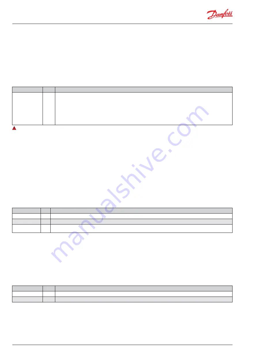
Related parameters:

Symbolic name

PNU

Description 

o30 Refrigerant

2551

1 = R12

2 = R22

3 = R134a

4 = R502

5 = R717

6 = R13

7 = R13b1

8 = R23

  9 = R500

10 = R503

11 = R114

12 = R142b

13 = User defined

14 = R32

15 = R227

16 = R401A

17 = R507

18 = R402A

19 = R404A

20 = R407C

21 = R407A

22 = R407B

23 = R410A

24 = R170

25 = R290

26 = R600

27 = R600a

28 = R744

29 = R1270

30 = R417A

31 = R422A

32=R413A

33=R422D

34=427A

35=R438A

R36=Opteon

XP10

37 =R407F

 Warning: Wrong selection of refrigerant may caurse damage to the compressor.

2. 

Connecting and setting up a valve

The EIM 336 controller is designed to be used with Danfoss

ETS 6 valves with a maximum of 480 pulses from fully closed to 

fully open. This setting should not be changed. 

The speed of the valve can be changed by increasing or 

decreasing the number of pulses per second, “n38 Max StepsSec”. 

A larger value will make the value open or close faster. Note that 

the torque of a stepper motor decreases as the speed increases. 

Too high speeds should therefore be avoided. For the ETS 6 valve, 

the recommended speed setting is 31 pulses per second.

When the controller is powered, the valve will first be closed 

fully so that the controller starts from a known opening degree 

(0%). In order to make sure that it is fully closed, the valve will be 

closed 100% plus an additional contribution known as backlash. 

The backlash takes into account that the stepper motor may 

loose some steps due to too low torque or mechanical slippage 

in the gears etc. The start backlash is the amount of extra steps in 

percent to close once the valve is closed (less than 1%). If the valve 

is opening and reaches its destination, it will move additional steps 

in the opening direction, then move the same amount of steps in 

the closing direction. This is called backlash and is the amount of 

steps to add to compensate for spindle play. 

Related parameters:

Symbolic name

PNU Description 

n38 Max StepsSec 3033 Steps per second
n39 Start BckLsh

3034 Backlash, is the additional amount of steps, in percent, to close at startup and when the valve opening degree is less than 1%.

n40 Backlash

3035 Start Backlash is the amount of steps to compensate for spindle play

3.

 Connecting and setting up a pressure sensor

The pressure sensor input is setup by default to accept an AKS32R 

pressure transducer. If another sensor is to be used, it is important 

to note that it needs to be a 0.5 - 4.5 V d.c. ratiometric type (10% - 

90% of supply voltage).

The default range for the sensor is 0 to 16 bar absolute. Thi s 

can be changed by setting the minimum transducer pressure, 

“o20 MinTransPres” and the maximum transducer pressure, “o21 

MaxTransPres” to the new values. The values must be entered in 

bar absolute so a sensor with a range of -1 to 12 bar gauge, needs 

to be entered as 0 to 13 bar absolute.

Related parameters:

Symbolic name

PNU

Description 

o20 MinTransPres

2034

Minimum transducer pressure (in bar absolute  x 10)

o21 MaxTransPres

2033

Maximum transducer pressure (in bar absolute x 10)

Summary of Contents for EIM 336

Page 1: ...ess noise The EIM 336 is the superheat controller that can be used to control the opening degree of a valve based on the superheat of the evaporator This is applicable in applications such as air cond...

Page 2: ...allation sensors 17 Warnings 17 Acronyms and abbreviations used in this manual LOC Loss of charge indication SH Superheat MOP Maximum operating pressure MSS Minimum stable superheat Te Saturated sucti...

Page 3: ...densed Superheat close When the superheat is below a set minimum value the valve will close faster in order to protect the compressor from the risk of getting liquid in the suction line Manual control...

Page 4: ...S2 PT1000 S4 PT1000 or digital input from external contact EEV driver Max current 150 mA EEV Uni or bipolar coil Data communication RS485 Modbus RTU Environment Storage 34 C to 71 C 30 F to 160 F Ope...

Page 5: ...odbus address stored in PNU no 40041 default 165 Jumper not mounted Outdoor unit condenser Modbus address stored in PNU no 40042 default 164 Com KM5 1 Drain D 2 RS485 TxD RxD 3 RS485 TxD RxD 4 Not Use...

Page 6: ...trol mode does not depend on the r12 Main Switch and will set the opening degree regardless of its setting Setting o18 Manual ctrl to 0 again the controller will assume normal control and will open or...

Page 7: ...secondary address is 164 Note Changes to these parameters will become active immediately This means that a modbus tool or controller that changes these settings will loose connection to the EIM 336 an...

Page 8: ...e controller is powered the valve will first be closed fully so that the controller starts from a known opening degree 0 In order to make sure that it is fully closed the valve will be closed 100 plus...

Page 9: ...sensor value will be used 5 Configuring the superheat control The superheat control algorithm will attempt to regulate the superheat down to the lowest stable value between the minimum superheat sett...

Page 10: ...um operation pressure If Pe goes above this value the controller will control on Pe and not on superheat Kp MOP 3113 Kp proportional gain while in MOP control mode Tn MOP 3114 Tn integration time whil...

Page 11: ...05 Timer to trigger LOC alarm LOC Alarm 50006 Loss of charge alarm flag 0 no alarm 1 LOC alarm LOC SH Trig 50007 SH error trigger level for LOC alarm LOC Tmr 3102 Loss Of Charge time readout displays...

Page 12: ...t regulation response Very low value give the risk of unstable regulation For Danfoss only 3105 SHL SH Low 3 20 6 K Superheat low setting for non linear control 3106 SHH SH High 8 40 16 K Superheat hi...

Page 13: ...ext S2 temp 200 200 0 C External S2 This value can be used instead of a sensor This register must be written at least every 5 seconds otherwise the sensor value will be used 2646 TS4 ext S4 Air temp 2...

Page 14: ...ain Switch 64309 Manual OD as steps 0 1 0 Enable the manual OD in o45 to be entered as halfsteps Readouts are still in percent Service Alarm 2046 RAL Reset alarm 0 1 0 1 clear alarm 20001 EKC Error 0...

Page 15: ...troller will go to either the low or high boundary de pending on the error The highest value will be shown if the signal is above the maximum value The lowest value will be shown if the signal is belo...

Page 16: ...it 3 Bit 2 Bit 1 Bit 0 Unused MOP Active Close Timer active Sensor Errors Control state Variables parameters CTRLstatus bit 0 3 Controlstate 0 closed 1 Error 2 Inject 3 De humidify 4 Force OD 5 Defros...

Page 17: ...ght after the evaporator If the measured value is 1 2 K lower than the actual value of Pe right after the evaporator it may cause the evaporator to flood This is the case when the pressure transmitter...

Reviews: